
Don’t let a half-cut solar installer install your half-cut (AKA split-cell) solar panels.
Silicon solar cells of the type now used for almost every residential solar installation in Australia have been around for a long time. They are 64 years old. This makes them the same age as nuclear power generation. They’ve come a long way since they were first made at Bell Labs in the United States. Originally they were only able to convert around 6% of the energy in sunlight into electrical energy but now the most efficient solar panels on the market manage 22%.
Unfortunately, the days of large improvements in efficiency have long been over. Now we only see small incremental improvements and one of these in use that will be much more common in the future are panels that use half-cut solar cells. These panels are known as both half-cut and split-cell solar panels.
Luckily, explaining what half-cut solar cells are doesn’t involve complex scientific explanations involving quantum mechanics. They are literally normal solar cells that have been cut in half. Instead of having 60 solar cells, as most panels put on roofs do, they have 120 half-sized ones. This results in lower electrical resistance that improves efficiency. An additional benefit is half cut panels resist the effects of shade better than standard solar panels. This isn’t directly due to the cells being cut in half but because of the way they are wired together.
While the increase in efficiency is only small, several large manufacturers are convinced modern production techniques make half-cut solar cell panels worthwhile. At the moment REC Solar‘s TwinPeak panels are the only half cut ones widely available in Australia, but with many large manufacturers either starting to produce them or planning to we will soon be spoiled for choice.
How They Work
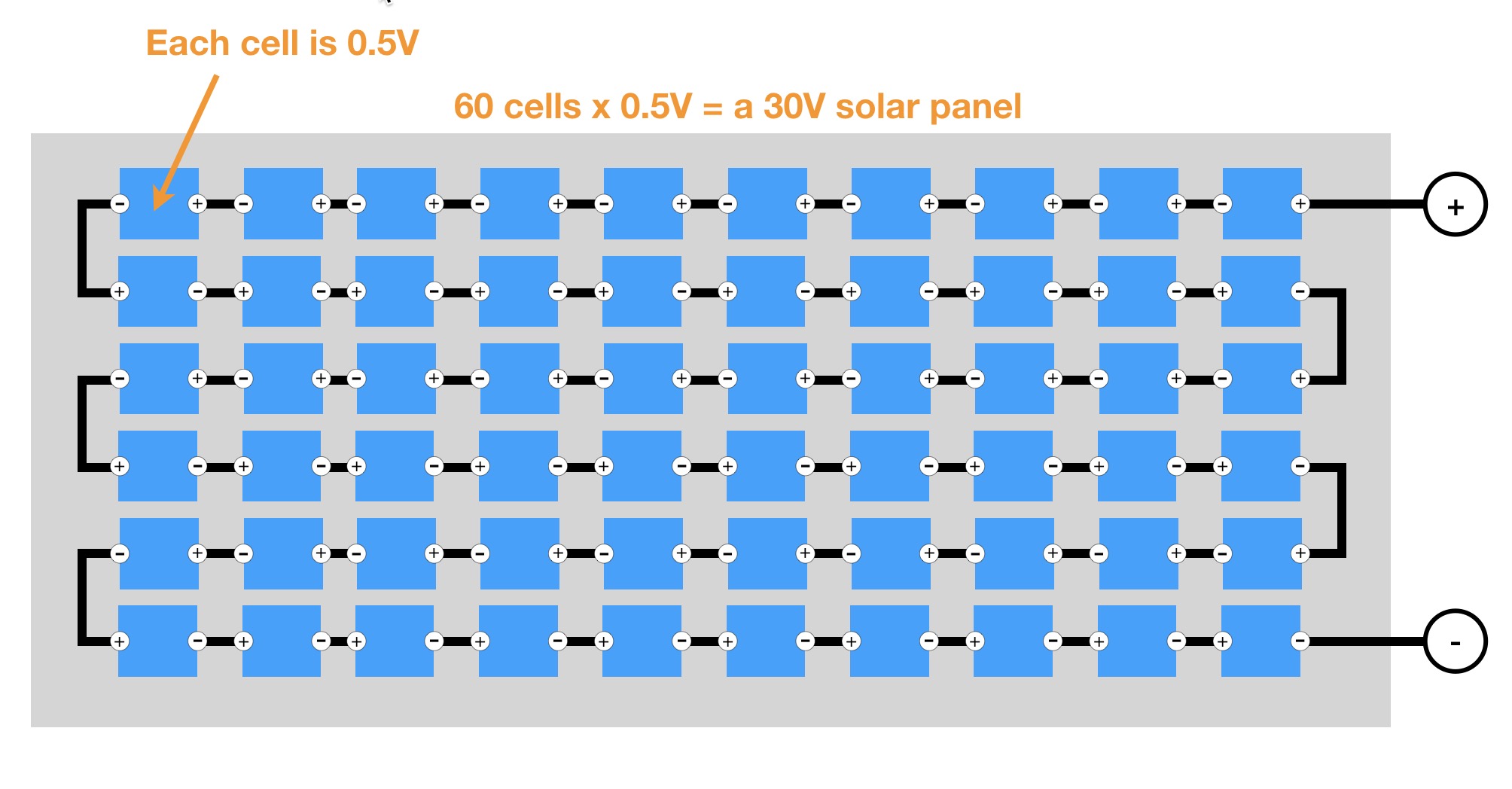
A conventional solar panel typically contains sixty 0.5V solar cells wired up in series. Voltages add in series, so this example solar panel operates at 30V.
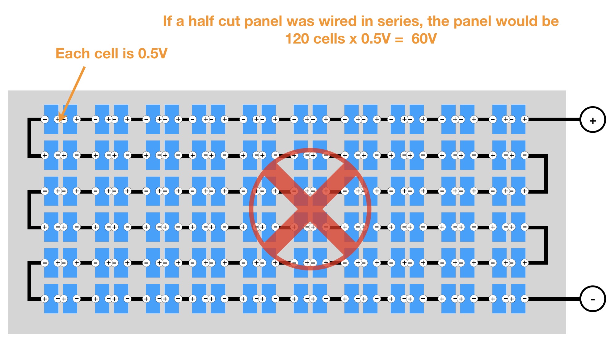
If you cut a solar cell in half it will produce half as much current, but its voltage will stay the same.
You’ll also have twice as many of them so, if half-cut cells were wired together as in a standard panel, they would produce twice the voltage.
This would not be appreciated by installers using normal solar inverters or trying to stay within Australian standards for residential solar voltage.
To make their voltage similar to standard panels the half-cut cells are wired together differently. There are 2 lots of sixty series-connected cells that operate at 30V each. These two 30V halves are then connected in parallel. Voltages in parallel stay the same, so the panel remains at the standard 30V.
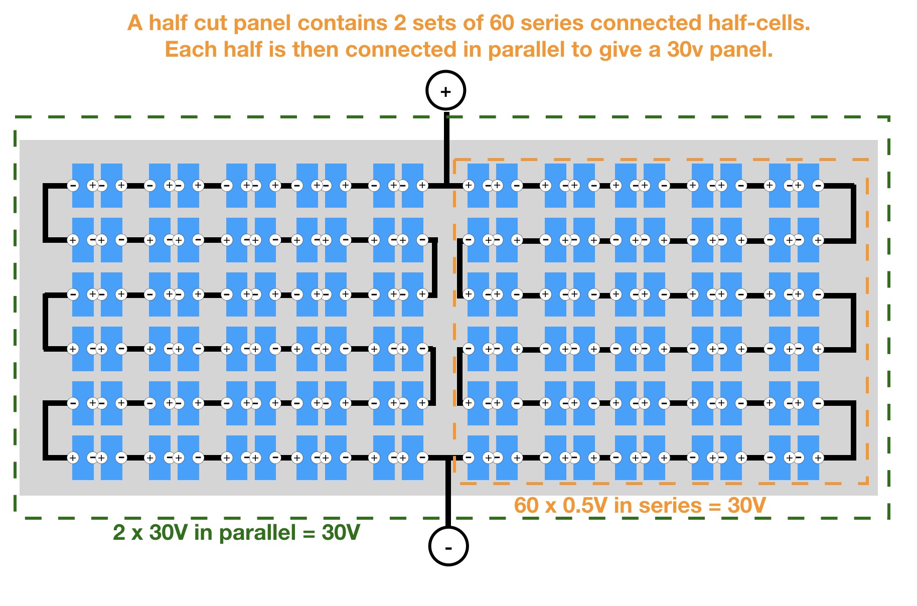
Bypass diodes not shown
Why are panel manufacturers going to the trouble of cutting cells in half?
Two main reasons:
- The lower current in each half of the panel means lower resistive losses. This increases the solar panel efficiency slightly.
- Improved shade tolerance in certain situations.
Shade Tolerance
A standard solar panel has 3 strings. Thanks to bypass diodes (shown in red below), one small spot of shade on a panel, caused by, say, a leaf or bird poop, will knock one entire cell-string out of action, but not affect the others.
Standard panel shade behaviour
Here’s what happens on a standard solar panel. The current flow is shown in orange, with the bottom bypass diode activated:
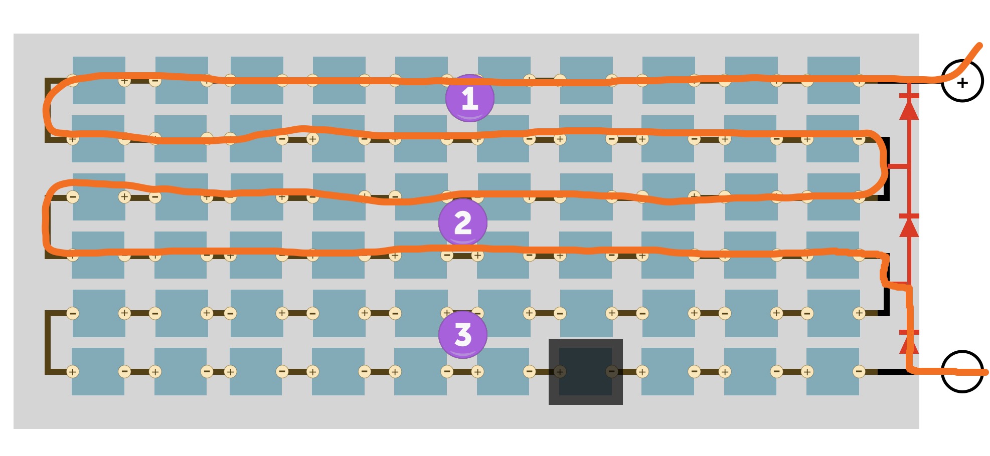
Two-thirds of the cells are active, so you get approximately two-thirds of the power.
Half-cut panel shade behaviour
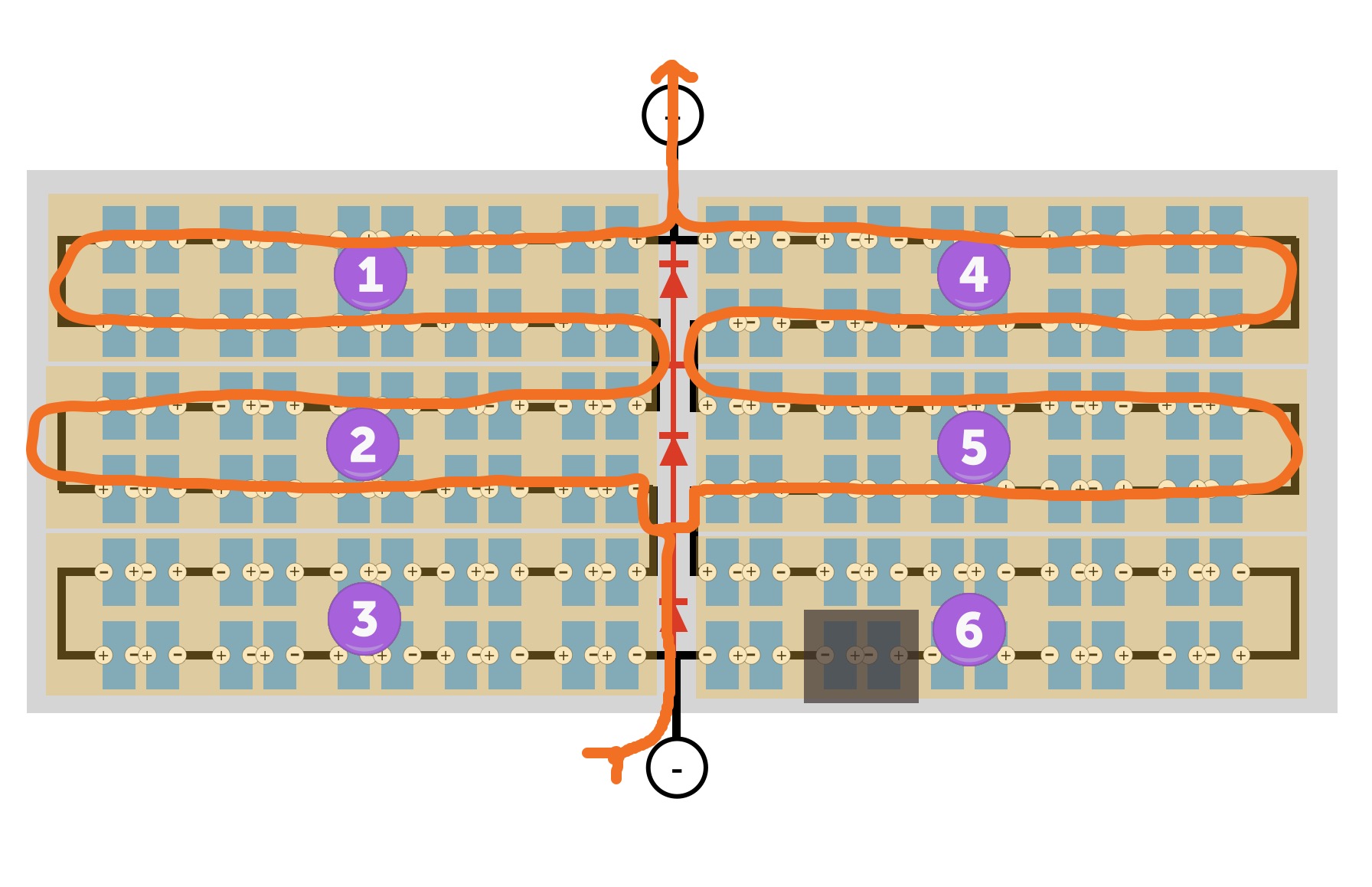
Instead of having 3 cell-strings like a standard solar panel, the half-cut panel has 6 cell strings making it a 6 string panel. One small spot of shade on a half-cut panel makes things interesting.
The current can either go through the bypass diode, in which case, only two-thirds of the cells are active – the same as a conventional panel:
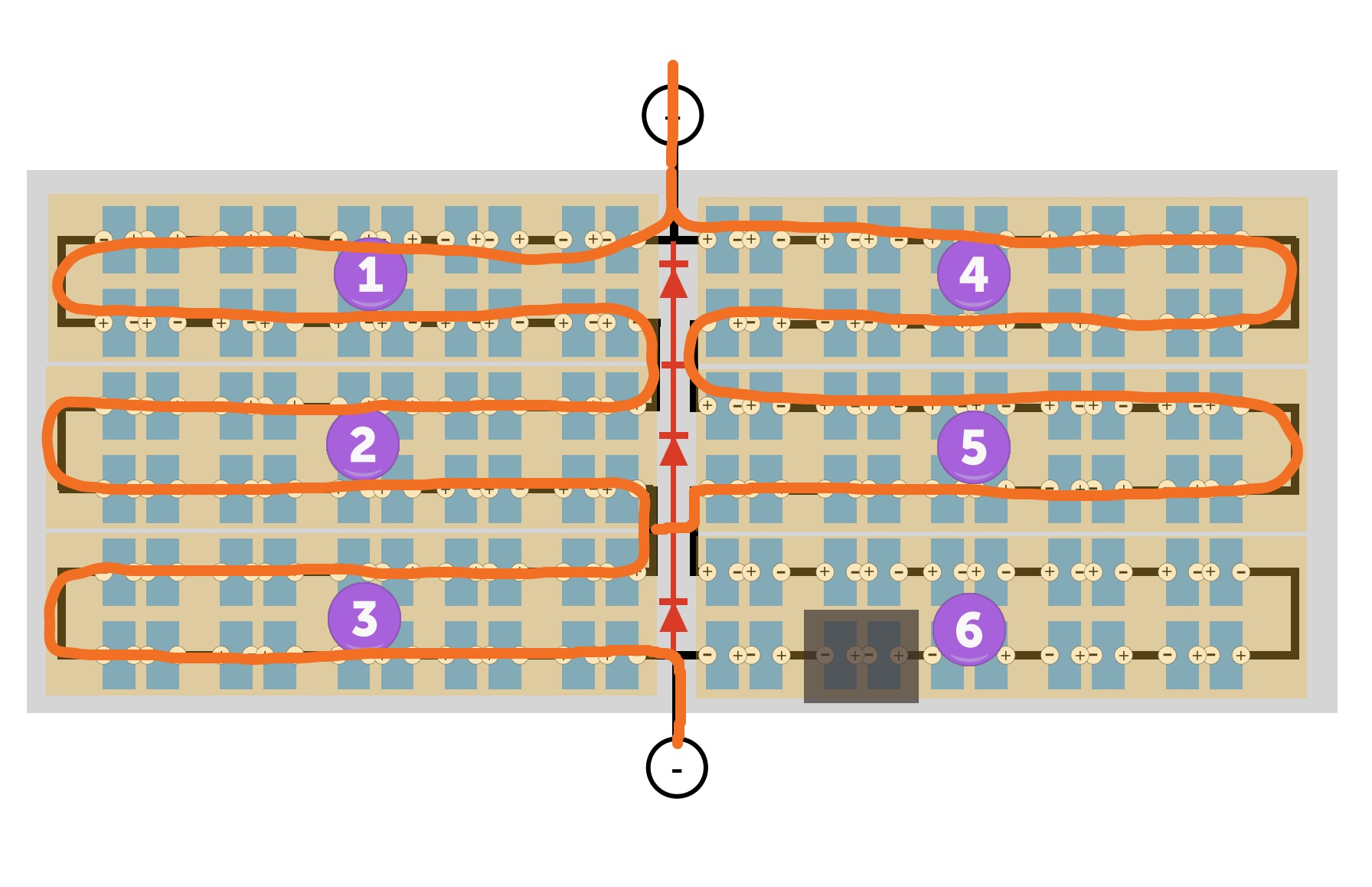
The alternative path for the current is via string (3), avoiding the diode, in which case five-sixths of the cells are still active.
Half-cut shade performance depends on your inverter’s MPPT algorithm:
You need a good inverter to make the most of half-cut panels. They need to find just the right amount of current and voltage to either activate or not activate the bypass diodes, to get the most power from the particular pattern of shade on the panel at that moment in time.
To make the most of a half-cut/split-cell solar panel’s improved shade tolerance you need to use an inverter with ‘Global Maximum Tracking’ MPPTs, so they don’t get stuck on the wrong power curve maximum. GSES’s excellent new video explains this really well:
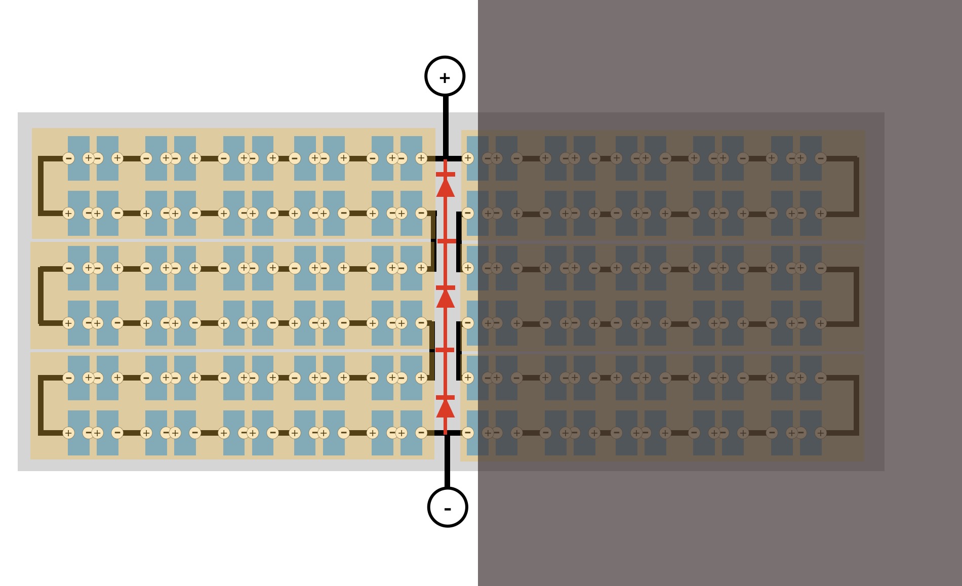
Shade should encroach from the short edge
To get the shading benefit of half-cut panels, they should be oriented so that shade encroaches from the short end:
Hot Spots Not So Hot?
When one solar cell in a panel cell string is shaded, all the preceding unshaded cells can dump the energy they produce into the first shaded shaded cell as heat. This creates a hot spot that can potentially damage the solar panel if it lasts for a long time. Twice as many panel cell strings means only half as much heat, but as the shaded cell only has half the area to radiate heat as a normal cell, I’m not sure there will be much of an improvement. But the decreased total amount of heat produced should be less damaging to the panel so there is likely to be an improvement in resistance to hot spot damage.
Split Junction Box
Standard solar panels have one junction box that cables come out of located on the back of the panel near the top. Panels with half-cut solar cells can have junction boxes that are split into three, as you can see in this picture of a REC Twinpeak half-cut panel. The middle box is for the middle bypass diode.
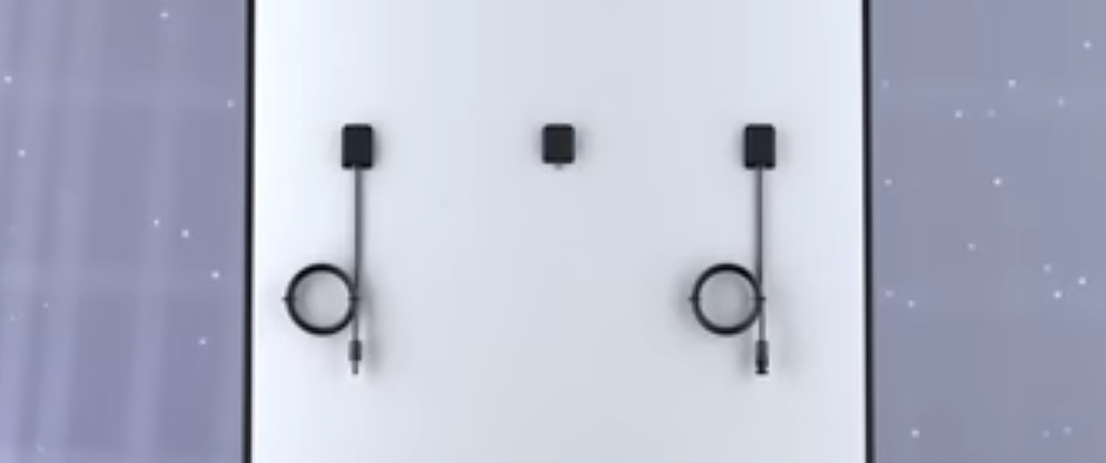
At first, I thought that since the junction box, or boxes, were in the middle of the panel it made no difference which way up it was installed. But then I was reminded that one cable is positive and the other is negative and it’s probably best not to confuse them. While there is enough length in the cables to cross them over if necessary, the thought of doing that gives me the creeps. It is not an elegant solution.
More Resistant To Heat?
I have read that half-cut cells are more resistant to the effects of heat and so won’t suffer as much of a decrease in efficiency when they get hot. And they will get hot if they have been installed properly, which is outside in the sun. But this may just be the result of the slightly higher efficiency of half cut panels causing more sunlight energy to be converted into electricity and less into heat. Looking at solar panel datasheets I can’t clearly see better heat tolerance compared to standard panels of similar efficiency. As information on more half-cut panels becomes available I might be able to arrive at a conclusion.
Half Cut Panel Disadvantages
Half-cut panels aren’t new. They’ve probably been around ever since someone accidentally broke some cells and decided to wire them together anyway. Solar cells used to be incredibly expensive so it must have happened a long time ago.
But despite having some advantages, panels with half-cut solar cells also had some disadvantages that prevented them from being put into widespread production until now. These problems were:
- Higher cost
- Twice the potential for soldering defects
- Internal cell defects become doubly dangerous
Higher Cost
Half-cut panels have the expense of cutting solar cells in half with a “laser”.
The laser that is used doesn’t even cut all the way through. It only puts a groove in the cell and then it’s snapped in two. This is apparently cheaper than just using a bigger laser.
Then there is the added expense of attaching twice as many cells to a panel and soldering twice as many connections. This would have resulted in a large increase in labour costs at the start of this decade when humans did most of this work by hand. Now it’s mostly done by machines that have lowered costs and improved reliability, so the increased cost per solar panel is not nearly as significant as it used to be and the reduced defect rate means half-cut panels can now pay for themselves.
Automation Solders On
Doubling the amount of soldering required doubles the chances of soldering defects. But apparently, modern automated soldering equipment is now so reliable this is no longer a serious problem and defects that do occur can hopefully be detected before the panel leaves the factory.
Halve The Cell — Double The Defect
Solar cells can have internal defects that reduce their efficiency. If a defect is very small it may not have much effect, but if you cut a cell in half you effectively double the effect of the defect. But defects can be found with machinery or even visual inspection if it’s large enough.
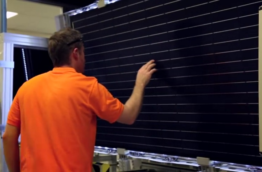
An Adelaidian inspects a solar panel in South Australia’s Tindo Solar factory. (Image Source: Tindo Solar)
These days machines can be taught to do visual inspections and, in the lab at least, they can do a better job of it than humans1.
Solar Industry Gearing Up To Produce Half Cut Panels
At the moment, the only half-cut panels I know to be in widespread use in Australia are REC Solar’s TwinPeak panels. Canadian Solar has recently introduced its half-cut Ku panels into Australia but refer to them as Low Internal Current solar panels. I can only guess this is because someone told them that in this country, half-cut means pissed as a parrot. My understanding is Canadians became very careful about what words they use in Australia ever since they found out what we think of root beer.
Large manufacturers that will soon be producing half-cut panels include:
Jinko Solar is the world’s largest manufacturer of solar panels and a representative of the company told me they plan to convert the majority of their production to half-cut panels. But he also told me he only joined the company 3 weeks earlier, so I’m not confident he would even know the best place to sneak a nap let alone have a good grasp of the company’s future plans. But I freely admit this was my own fault. I had a clear choice. I could have spoken to the guy who knew what was going on or I could have spoken to the guy who knew English. I chose poorly. I should have rung up to the experienced guy and hit him over the head with Google Translate. Then I’d be able to confidently tell you that Jinko’s hovercraft is full of eels.
Final Thoughts
Because their issues with defects appear to have been resolved I would be fine with selecting a panel with half-cut solar cells over an otherwise identical standard panel because I would expect slightly more output from them thanks to their being better able to deal with shade.
Footnotes
- There’s even a guy who says we shouldn’t train radiologists to examine x-rays anymore because machines are starting to do it. And there are those who disagree. ↩
 RSS - Posts


shading is always a problem for cells or panels in series. 30V on a panel does not really help. SF CIS panels are about 82V at mpp, so ideal for direct 48V battery charging. the higher voltage shows that multiphase dcdc converters for MPPT benefit in ripple current and operational life from that ratio. victrons are 2 phase, but I have seen chinese 3 phase converters profiting even more.
Would further gains be achieved by cutting into 1/4’s or 1/8’s or greater?
Potentially yes, but that would run into diminishing returns pretty quickly. Another method of making panels involves cutting one cell into 5 strips and overlapping them and I doubt manufacturers will go much beyond that with silicon cells, but I guess I could surprised on this.
Just a point about the diodes. You said in the article:
“On a standard panel this will reduce output by one-third while on a panel with half cut solar cells it will only reduce it by one-sixth.”
The laws of how electricity flow mean that this cannot be the case. If the diode is operating on the half-cut panel then there will be zero voltage across both cell-strings connected to the diode and so both will be bypassed.
What the two cell-strings do mean is that you could theoretically have different amounts of current flowing through each half of the panel. This would be particularly useful if you have similar shading across an entire string of panels, e.g. if the bottom half of all the panels were shaded then you’d get a lower current flowing through the bottom half and a higher current through the top half with the same voltage across both (usually around 30V on a standard-size panel). Standard panels in the same situation would have their entire output cut by the bottom half being shaded and even if installed horizontally so that the bypass diodes can help by bypassing shaded cells, the shaded cells would produce nothing when the half-cut panel may allow both to produce a near-optimal amount of power.
I don’t think the effect would be large unless you have some very specific shading patterns, but it could help a bit.
Great point. I’ve edited the post to fix that error.
Here’s how the shade tolerance is improved by a half-cut panel (from a REC paper). It is better, but not 2x better:
Sorry Ron, but I can’t agree with your paragraph:
“If you cut a solar cell in half it will produce half as much current and one fourth as much resistance. But you’ll have twice as many of them so, if they are wired up to operate like a standard solar panel, you will have the same current but with half the resistance. This lower resistance reduces electrical losses and improves panel efficiency.”
If you cut a cell in half, then re-join it, you’ll end up with exactly what you started with. A join in the middle doesn’t add magical properties.
The small increase in efficiency is due to the greater area of metal interconnecting the strings of half-cells.
The bigger benefit is in reduced degradation from leaves etc. shading cells.
Finn, there’s a graphical “typo” in your diagram. The halved cells are connected as two _parallel_ strings, not series. When Ron writes of half the current and 1/4 the resistance, he’s mixing measures of a single string and the pair, I believe.
The generated photocurrent of a single string of cells, and two parallel strings of split cells will be the same if they have the same total area and efficiency. (But, yes, they produce half that current each in the split case, as Ron wrote.)
When Ron writes “you will have the same current but with half the resistance”
for the two parallelled strings of half cells, it means that each split string still has the original resistance, and its internal power loss is 1/4, due to the halved current. (I^2R) That would be half the loss for the pair of strings. If there’s half the resistance in each split string, we’d have 1/8 the loss in each, (0.5^2 * 0.5), which is 1/4 the loss in the pair. which may be what Ron meant with the phrase “one fourth as much resistance”.
To clarify, we need to establish what happens to the cell resistance when it’s cut in half. Total interconnection resistance may be approximately halved if the metal track cross-sectional area remains the same. (But is any exposed cell area sacrificed for that?)
If alternate columns of half cells are inverted, can they be more closely tesselated? (Pointy bits interleaved for partial column overlap.) That’d increase panel output for silicon & soldering cost only – no extra frame or glass cost.
Maybe the way to look at it is like this. Imagine each cell is a sheet of resistive material with a current source in series with it. If you cut a cell in half crossways, the length will halve but the width stay the same. So the resistance will halve but the current will halve too. Since the loss is proportional to the current squared, the series loss is 1/8. There are two half cells so the total resistive series loss is 1/4 of a single square cell loss. As far as the shunt loss is concerned, this is modelled by a resistor as shown in the diagram. Halving the area doubles the resistance so putting 2 together gives no change.
In the diagrams from the paper referenced, the half-cells are in series but the power loss calculation whether series or parallel would be the same.
This is simplified. The journal paper is worth a look
Explain to me how cutting a cell in half results in two cells with a quarter resistance!!! It doesn’t ..each has half resistance !!! This must be a lie perpetuated by manufacturers of these panels …..
There are savings to be had by having a higher operating voltage , but this can be achieved by putting whole cell panels in series …
By splitting the cell to two half-cells you indeed devide the length in half, but you need to have a reference to your previous module. Imagine the bus bars of each cell collecting along their their the free electrons on the surface of our p-n diode. Assume the length of the cell is L.
For a whole cell the current of the upper layer of the bus bar is equal to I(x)=I_bb*(x/L), while I_bb is total current that the collector receives (the big wires perpendicular to the bus bars) from each bus bar.
Now you have to integrate I^2*dR in order to get the power consumption where dR is equal to r*dx/S from x=0 to x=L for both sides of the cell. Divide by I_bb^2 and you get the resistance of each bus bar.
To get the whole resistance you have to remember that the total current of the cell is equal to I=I_bb*N_bb where N_bb is the number of bus bars. Now all you have to do is divide the total power consumption with I^2 and that’s it.
Now in order to find the resistance of 2 half-cells (=1 whole-cell) you just have to change I(x) to (I_bb/2)*(x/(L/2))=I_bb*(x/L).
It’s the same!
Now integrate I^2*dR with the same dR but with different bounds (from x=0 to x=L/2).
Doing the same thinking you will get that the resistance of 2 half-cells are actually a quarter of the whole-cell.
To be precise R(whole-cell)=(2*r*L)/(3*N_bb*S) and R(2 half-cells)=(r*L)/(6*N_bb*S).
Thanks for the explanation, Rizeakos! Now, just let me take off my shoes and socks so I can check that…
Could someone please explain to me what happens if a string of 6 panels has one totally shaded with the others in full sun. To what extent would that situation affect the current flow?
Would the diodes in the shaded panel allow the current from the other 5 panels to flow freely to the load, or would the output from the other 5 panels be noticeably reduced.
Thank you in advance to anyone who could help me to understand what happens in this case.
Hi Peter
This isn’t exactly what you asked for, but if you go to 3 minutes and 17 seconds in the video in this link…
https://www.solarquotes.com.au/blog/solarquotes-tv-ep8-mb2146/
…you can see Finn do a real world test where he covers a single solar cell and a larger area of solar panel on a fronius inverter system and an Enphase microinverter system. There are also links to more detailed testing.