
Electrical devices have many different ratings, but one of the most confusing distinctions for the average consumer is between kilowatts (kW) and kilovolt-amperes (kVA).
Kilowatts vs. Kilovolt-Amperes: Decoding the Jargon
Half of humanity confuses the relatively easy-to-explain kilowatt-hours with plain kilowatts (you’ll find some good references here for kWh vs kW).
But hold onto your hat, because the concepts I’m explaining below are a bit more abstract.
The classic trade-school explainer on kVA and power factor involves a pint of beer. The useful part is the glorious amber liquid you can drink — that’s active power. But on top there is always that white foam; simultaneously useless and indispensable — that’s reactive power.
If you’re now confused and thirsty, don’t worry. I assure you most apprentices are too. But bear with me while I try to draw a picture with words.
(And if you’re an electrician, retired engineer or similar pedant, please go easy in the comments section. We’re here to help the punters.)
Calculating Kilowatts
Getting a handle on kilowatts isn’t too hard, we’ve run through it before with a simple ohms law calculation.
- Take the ordinary mains supply of 230 volts (this is the pressure that drives an electrical circuit).
- Multiply 230 by the amperes required (the measure of current, or flow of energy needed by the device).
- For 8.7-amps, for example, the result is 8.7 x 230 = 2,000 watts, or 2kW.
This would be enough energy to run a fan heater, kettle, toaster or small, conventional hot water service. These are simple resistive loads, just like a bathroom heat lamp.
Other similarly heavy loads could include a pool pump, air compressor or split-system air conditioning unit. However, these are inductive loads. They have large inrush currents, so they’re difficult to start. They also react with, and cause distortion on, the mains supply.
That reaction or distortion has a separate rating: power factor.
Kilowatts (kW) represent the actual active power used for doing useful work.
Kilovolt-Amperes (kVA) refers to the apparent power. That is, the working power plus the reactive power factor — which does not do the useful work, but is necessary to maintain the voltage levels in the system.
Real-World Applications of kVA and kW
In practical terms, most people aren’t aware of the differences between kVA and kW until they go camping and want to buy an inverter or petrol generator for power. The local tool shop will have machines rated in kVA, and they’ll sensibly advise buying more than you need.
-
- For your 2kW-resistive crab-cooking pot, a 2kVA generator may be sufficient.
- However, an air compressor (inductive load) would need at least 2.5kVA capacity to run.
- Additionally, the surge required for starting an induction motor would demand the generator put out at least 10 to 12kVA.
A Different Type Of Horsepower
Imagine a horse (electrical system) pulling a cart (load) along a road. The effort the horse puts into moving forward is the actual work (kW) being done to move the cart.
However, if the road is boggy dry sand, the horse needs to exert extra effort just to maintain its footing.
In every step, energy is used pushing sand around. This doesn’t directly contribute to moving the cart forward, but it is necessary to complete the overall task.
The total effort (kVA) combines both these aspects: the actual moving forward plus the effort to plough through the sand without slipping.
In ideal conditions, the road is smooth and hard, so all the horse’s effort goes into moving the cart forward (meaning kW equals kVA). But in reality, roads can be boggy, requiring more total effort (kVA) than what directly contributes to the movement (kW).
Ideal Loads vs. Inductive or Capacitive Loads
-
-
- Ideal Loads (Unity Power Factor):
Ideal loads enjoy a ‘smooth road’, meaning all the power supplied (kVA) is used as effective work (kW).
The power factor in this scenario is 1 (the unity power factor), indicating no difference between kVA and kW.
- Ideal Loads (Unity Power Factor):
-
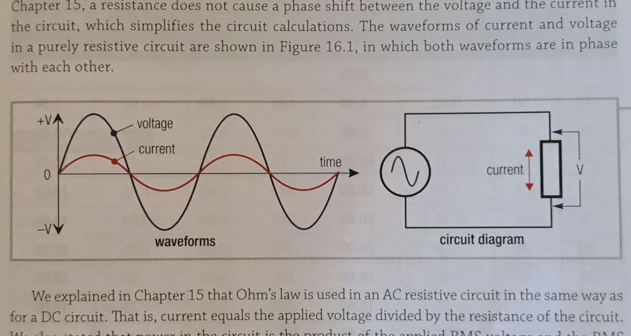
A simple single-phase AC wave with current in perfect unity with voltage. Image credit: Phillips 1996.
-
- Inductive or Capacitive Loads:
Inductive or capacitive loads introduce a ‘boggy road’, whereby part of the power (reactive power) does not do any useful work, and instead creates a phase shift between voltage and current.
This scenario requires more apparent power (kVA) to do the same amount of work (kW), decreasing the system’s efficiency. Excess reactive power can also potentially cause overheating and damage.
- Inductive or Capacitive Loads:
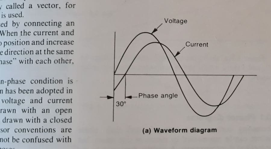
An inductive load ‘bogs down’ the current, causing it to lag by 30°. Image credit: Jenneson 1980.
It’s A Slippery Concept
For a little nerdier detail, imagine an AC wave. The electricity coming from your wall socket alternates between 230-volt peaks and troughs, crossing through zero in between, at a frequency of 50 Hertz (Hz). This frequency is what your oven uses to keep time.
In an ideal resistive load, the voltage and current are perfectly synchronised. As the voltage pushes, the current rises obediently, and as voltage ebbs, the current drops. They rise and fall together in harmony and it’s all very efficient.
With an inductive load you could say there’s inertia. The voltage might rise but the current lags behind, so you need more energy to get it moving.
However, once the current is underway, it resists the change in pace when the voltage falls again, and arresting this runaway current takes more energy again.
What you see is the current ‘reacting’, or pushing back on the voltage that it should be skipping along with in harmony. It even has a unit of measurement called Volt-Ampere Reactive (VAR).
A capacitive load has a similar but opposite effect. When you apply a voltage to an empty capacitor, there is so little resistance, current will pour into it in a fraction of a second.
To use a water-based analogy, it’s faster than upending a bucket and waiting for gravity to draw the water out. Rather, it’s like opening a portal to space, where the water disappears into a vacuum quicker than you can blink.
Electrically, this means the current will lead the voltage, which is supposed to be pushing it along.
No matter which is leading or lagging, the difference between voltage and current is the power factor. It creates waste heat in your wiring, motors or appliances, and requires extra energy to be supplied by the mains transformers on the street.
The fun part is that grid-connect solar inverters can be programmed to help support the grid, and since AS4777.2020 standards came into effect, installers have been obliged to select or program inverters to raise or sink VARs depending on grid voltage.
Phase angles: This is how you convert the push-pull of an AC wave into a rotating motor.
Ratings Can Be Deceptive
My own Honda generator has a model number 3.0i, arguably suggesting 3kW capacity. But it’s actually only rated for 2.8kW.
Victron (which I really like) offers a mind-bogglingly comprehensive array of different inverters, chargers and regulators, all integrated with various sensors, displays and monitoring. There’s nothing better in a lot of situations. However, if you take them at face value, the inverter chargers we use for remote-area power just don’t do what they say on the tin.
A blue box with a part number 5000/48/75 implies that the system is capable of 5kW. It’s actually 5kVA. And in truth, with a power factor of 0.8, that means a nominal output of 4kW.
Worse still, as a 48-volt battery charger, this system would be rated for 75amps. So the real continuous rating for this machine is 48×75, an honest 3.6kW. You just have to be aware and size them to suit.
Be Alert But Not Alarmed
The difference between kVA and kW is important when designing and operating electrical systems, and this is why network companies specify maximum inverter capacities in kVA.
For the end user getting a solar connection approval, it’s good to have an understanding of these things. But, honestly, for a consumer buying solar, the terms are basically interchangeable.
 RSS - Posts


How to react to this post?
I am not sure I have the capacity needed to absorb it all.
I will join all the laggards and sit at the back of the bar supping froth.
Great article.
Engineer here.
A few errors in the article that can hopefully be fixed.
1) Unfortunately the articles uses the words energy, work, power interchangeably at times. But they have different meanings:
– Power – Measured in Watts (P=I*V)
– Energy – Measured in Watts Hours (E=P*T)
– Work – Measured in Joules
Work, Energy and Power are fundamental concepts of Physics. Work is said to be done when a force (push or pull) applied to an object causes a displacement of the object. We define the capacity to do the work as energy. Power is the work done per unit of time.
2) Inductive loads have LOW in-rush currents. This is why Voltage leads Current for inductive loads.
An inductor will resist changes in current.
However, motors will have large inrush currents because they need to use a large ammount of energy to spin the motor. Once the motor is spinning, the energy requirement is reduced.
Yes, motors are inductive, but inductive does not mean large in-rush.
3) “Kilovolt-Amperes (kVA) refers to the apparent power. That is, the working power plus the reactive power factor”
The power factor is a multiplier (hence the name factor). Typically something close to 1.0, but can be as low as 0.2.
As an example lets use a PF of 0.6 with a load of 2kW.
kVA=2kW/0.6=3.33 VA
4) The RMS Voltage of the wall socket is 230V, however that means the Peak to Peak Voltage is 325V (230 * sqrt(2))
5) The concept of inductors and capacitors is also a little bit off.
It’s helpful to think that:
– Inductors resist changes in current
(and hence Voltage on the AC line will lead)
– Capacitors resist changes in voltage
(and hence Current on the AC line will lead)
6) It’s important to note that apparent power does not actually equal power (hence the word apparent).
No work is done by apparent power, no extra energy is consumed by apparent power.
Yes, extra Voltage and Current is provided, yes wires need to be rated for higher currents.
But no, extra power is not consumed.
It all comes out in the wash
Thanks Paul,
There’s always an engineer somewhere in the crowd 😉
With the utmost respect, Paul – I think you too have confused a couple of things.
Firstly, Power is the rate of doing mechanical work OR of transferring electrical energy – they are essentially the same thing – no distinction.
Not surprising really – you say Energy is measured in Watt-Hours, and Work in Joules. But, Paul, a Joule is a Watt-second – by definition. Divide Joules by 3600, and you get Watt-Hours. It is just a scaling issue – nothing fundamentally different in the nature of these (divide Watt-Hour by 1000, and you get kWh). Energy & Work are measured the same.
Also – the large inrush current to an electric motor is more to do with their low resistance. This high current will accelerate the rotor quickly – but this is more a consequence than a cause. Yes, much of this energy is converted to kinetic energy in the motor inertia – but somewhat inefficiently due to high i2R losses, and magnetic saturaton effects. As the motor accelerates it generates an increasing back-EMF – which opposes the applied voltage to lower the nett voltage across the low resistance (and inductance), thereby lowering the current draw.
Paul – you are correct about Apparent Power – but that is not the whole story. Inverters require designs that can handle both voltage (so their components don’t break down), and current (so their conduction pathways and thermal dissipation capabilities are not exceeded). So – Anthony is correct – you buy an Inverter really based on voltage and current (VA) of design capacity, but the Power they can deliver is measured on Watts. If the Power Factor is 1, then VA = W, and all is good. However, if the inverter is driving a bank of (uncompensated) fluorescent tubes (poor PF), it would need a higher VA rating, than total tube power rating.
DNSPs don’t like a poor PF behind you meter – as the meter measures power, but they are hit with all the extra i2R losses through their network due to the higher current being drawn.
Cheers Ian, and Paul,
Having tried to break down the concepts for the punters, when the learned commenters get stuck back in with the finer points of jargon I recognise, I think I learn as much as anyone from these exchanges.
Thanks.
With regards to Energy/Work, agreed they are the same units.
But scaling factors mater. People don’t measure Volts in Electron Volts. Gas is measured in Mega Joules, Electrical Energy is measure in kWh, work is measured in Joules. But the article uses work/energy/power interchangeably, this is not correct. This will lead to confusion by the readers on an article that is meant to clarify a technical subject.
With regards to motors, yes motors have low resistance, which means large currents. But read the article. The article is switching between cycle-by-cycle analysis, and then switching to macro, multi-cycle analysis. This is confusing to the reader. I presented a simple argument that allowed for the reader to understand both the inductive properties of motors, and also the macro model of motors. I could have have brought the resistance/impedance/backemf into the discussion, but that’s not going to help people understand kVA.
With regards to apparent power, agreed that things need to be rated for the kVA. But its important for the reader to understand that kVAh != Energy.
(Many people, including engineers and electricians do not understand this).
In the article statements like “In every step, energy is used pushing sand around” or “Inductive or capacitive loads introduce a ‘boggy road’, whereby part of the power (reactive power) does not do any useful work, and instead creates a phase shift between voltage and current.”
It’s not just kVA doesn’t do any useful work, it does _no_ work. It also doesn’t create the phase shift. The phase shift is caused by the inductive/capacitive nature of the load.
Yes there is current, yes there is I2R loss, yes these must be generated, but AP does not _do work_.
(That quote on the buggy is an example of work/energy/power/reactive/current/voltage/phase all getting mixed up to produce an incorrect analogy).
One final point, just so its clear, end user (households) don’t pay for apparent power, only real power.
Paul and Ian – I enjoyed reading your exchanges. Helps me remember my electrical engineering from 50 years ago and the difficulties I had in understanding it all. And Anthony – a difficult subject to tackle – Thank you 🙂 – Frank
Clearly for those of us non tech electrical people, the take home message seems to be to make your system bigger than you think you need.
While we are forced to pay 50c/kwh at the beginning and end of day for power purchased, we can get a great return on the extra invested panels on the roof when we oversize and use that sunshine energy instead of buying power.
Well said Paul, you know what’s Watt.
Thanks Anthony great explanation, as a IT infrastructure engineer I’ve spent many hours calculating UPS requirements and never really understood what the power factor was, I’m all over it now.
Great article! Took me back to my apprenticeship days 40 + years ago. Clear and digestible analogies to explain PF.
Well done Anthony!
Great article Anthony,
I studied Electronic Engineering in the early 70’s and don’t remember this being covered at all.
I do remember the difference between peak voltage and RMS voltage.
I always thought kVA was peak and kW related to RMS or effective power but you have enlighted me with your glass of beer example. Cheers. Peter
I confess I’m still somewhat confused, though this article is perhaps timely. If dealing with a 750 W PSU, what size VA should your UPS be? : – )
I see one system claiming 510 W and typical runtime of 35 minutes, but it’s all rather confusing!!!
Hi George,
Generally if you have a load that causes a lot of reactance, a device that causes poor power factor losses then your UPS needs to have more VA.
Your 750watt load would at worst need a 940VA power supply, call it 1kW to be safe.
(If the PSU is a nice clean load, and it doesn’t draw the full nameplate 750w continuously, a 510w backup unit might suffice?)
If it’s a 1kW inverter you need enough battery to deliver that energy for however many hours you want.
1kW for 35minutes means you need a 583wh storage capacity (or around 50ah if it has a 12v battery?)
I’m pretty sure that’s how it breaks down.
I remember “ELI the ICE man”
Voltage Leads Current for Inductive loads,
Current Leads Voltage for Capacitive loads.
Great Article Anthony. My son is a 2nd Year apprentice Electrician and the tafe teachr was not doing a good job of explaining these concepts.
Have forwarded it onto him to better understand
Craig
Extra points for the capacitor inrush being more like a portal to space than a bucket!
OMG, analogy of the year
Thank you Anthony, great explainer. It has always helped me to understand things by looking at extremes. For instance, say we have an ideal transformer with no load connected to the secondary coil. Connecting it to AC power, we then get a phase shift of 90deg meaning it should not consume any power as the average of current x voltage over a whole cycle is equal to zero. This is despite the fact that we actually connect active and ground with a continuous length of copper wire. So nothing gets consumed, no electricity to pay… uhm … right???
In a perfect world there’s no losses so yeah that’s my understanding. Zero load on the secondary means reactance in the primary winding limits the primary current.
I still recall a TAFE lecturer who said “it’s voodoo” that a transformer can turn voltage into current and vice versa, with no moving parts, as he tried to explain a 12volt ignition coil could put out 40,000v.
MeiniOz, you’re delving into deep waters here. (At uni I scurried off into digital electronics to avoid the maths and weird stuff with magnetics, but a little bit rubbed off later, while working with analog engineers who relished this stuff.)
Firstly there’s core losses, proportional to the area inside the hysteresis plot for the core material. This B-H graph plots magnetic field strength against flux. The energy is lost as heat in the core.
Then there’s eddy currents, induced in the core if it conducts. Laminated iron cores have at least an oxide layer on one side, or a thin synthetic insulation film, to stop that – mostly.
Then there’s I-squared-R losses in the primary, small on no-load, as we’re only powering the other losses.
The inter-winding capacitance is a miniscule factor at 50 Hz, negligible if the windings are on separate core arms, and can be ignored here.
The schematic then has winding resistance in series with primary and secondary, plus a shunt resistance for the core losses, I figure. The current is then at less than 90 deg to the voltage, and some real power is consumed. (The 90 deg component rattles back and forth in the network, eventually being consumed in line resistance, if I recall with any accuracy. That’s unprofitable, so low PF is not well accepted.)
That’s about as much as I remember from well back in last century, apart from leakage inductance, which is due to the flux lines from the primary which do not couple to the secondary, if wet RAM is still working. That’d only contribute to losses if it coupled into adjacent iron, and would be small on any well designed transformer, anyway.
There’s nothin lossless in practice; many decades ago I bought a cheap Chinese transformer, and it ran alarmingly warm on no load, due to crappy iron, so high core losses.
‘nother retired engineer here. I’m impressed with the very creditable effort to make a slightly techo concept much more digestible. That initial graphic is a bottler – one I hadn’t seen before.
I did worry about the compressor example, until the inrush factor was mentioned in timely fashion. (And I guess most won’t care that back pressure on the compressor only extends the surge, and it’s the fact that a squirrel cage induction motor is essentially a transformer with short circuited secondary, and it’s only the back EMF when it spins up which brings the current back to sustainable levels.)
When my two 8 kVA Victrons turn up Monday week, I can easily start the 2 kW compressor without relying on the pair of Fronius PV inverters for a leg up. An important related consideration, at least for off-grid, is how badly that flogs the battery. With 46.5 kWh installed, that’s only 0.27C, with losses, even during the 12 kW starting surge. (OK, yes, one 8 kVA Victron would probably do it, with its short duration surge capacity, but redundancy is peace of mind when off-grid.)
I figure that the EV charger will have a pretty good power factor … hopefully at least, as it’ll be doing a good deal of work at the significant power level of 7 kW for the whole sun-rich day after a decent trip.
Cheers Erik,
As far as I know the power factor with EV chargers is good, in fact for some years now SAPN have been happy to have them on controlled load metering when the only other things they allowed were resistive elements in hot water services & slab heating.
Nice article & analogy.
In your Victron observation a power factor of 0.8 is used which corresponds to their data sheet comparison of VA & W.
Victron data sheets, in a note to their VA ratings, refer to ‘Non-linear load, crest factor 3:1’. How does crest factor relate to power factor?
Secondly, what power factor is normally used in a household to size for VA?
Okydoky, dumb question expecting to be slammed- here we go…
So things that just use resistance to create heat have a flat use profile?
And things that need to get a motor spinning in a tube of magnets need some extra juice, a bit of Ooomph?