
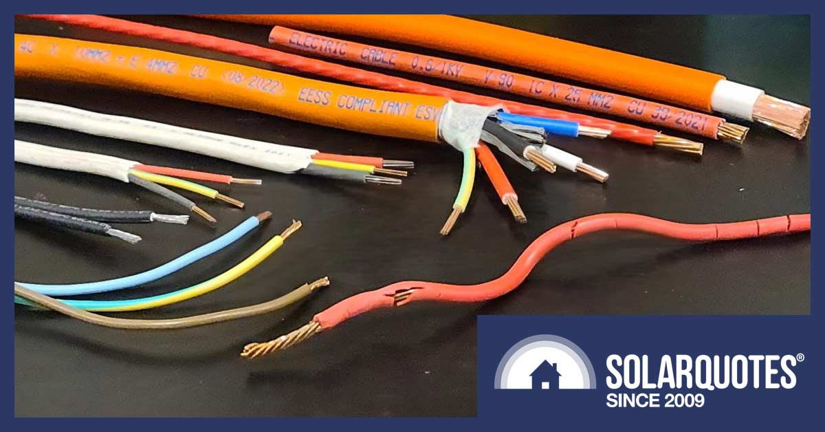
Top to bottom, 70mm² 25mm² 16mm² 10mm² (3 phase) 6mm² sheathed, 2.5mm² sheathed, 4mm² Solar DC, 3 x 2.5mm² flexible plus a dangerously cracked and brittle 16mm² main service from a 1960s house.
Some weeks ago, I explained why the voltage in a long cable will drop over its length, and how this affects solar installations that are a long way from the switchboard.
Note: I call this a voltage drop, other people call the exact same phenomenon a voltage rise. It just depends on your perspective. Just like when I go to the bar: I experience a dollar-drop, the bar-owner experiences a dollar-rise but it’s the same transaction.
In this post, I’ll explore the finer details of voltage drop. I’ll provide details you can use to sort the wheat from the chaff (or the plumbers from the electricians). I’ll keep it as simple as I can, and then at the end, share some advanced insights for the true geeks.
Plumbers Can Help Us Understand Voltage Drop
There are only two things you need to know to be a plumber:
- Shit flows downhill.
- Payday is Thursday.
You need to know a few more things to be an electrician:
- Given half a chance, electricity will kill you.
- There will always be losses in a cable. Losses = voltage drop.
- If you need a stepladder, borrow the plumber’s wallet and stand on that.
The funny thing is that as an electrician, you often have to borrow the plumbers’ vernacular.
- Voltage (Volts) in a cable = pressure in a pipe.
- When the water flows down a pipe, there is a pressure drop (AKA losses) from one end to the other. When electricity flows through a cable, there is always a voltage drop from one end to the other.
When dealing with grid electricity1, the ‘pressure in the pipes’ is 230 V. Australian Standard AS 60038 dictates it should not drop below 216 V or exceed 253 V.
With such a limited range of pressure available, the adjustments available to the humble electrician to manage the voltage drop are:
- The cross-section of the pipes used. AKA cable thickness (mm2). The fatter the pipes, the smaller the losses.
- The length of the pipes. The shorter the pipe, the smaller the losses.
- The flow rate in the pipes; aka electrical current (Amps). The slower the flow, the smaller the losses.
5% Voltage Drop Allowed For Non-Solar Electrics
Electrical rules (AS3000) say that for any home (whether you have solar panels or not):
- From: the “point of supply” on your premises (which might be the fuse on the eave or the retail meter box)
- To: the farthest power point or light
…no more than 5% loss2 at full load is allowed3.
Only 2% Allowed For Solar
For solar power systems, the rules are more stringent. Australian Standard AS4777.1 stipulates a maximum 2% voltage drop from the solar inverter to the ‘point-of-supply’ (where your house connects to the grid).
Whether your installation abides by these two rules will depend on:
- The length of the cables
- The thickness of the cables
- The maximum current through the cables
- And how much loss has already been built into your existing supply cabling.
A good solar installer will visit your home before any firm quote to measure the distances involved and existing cable thicknesses. These numbers will go into a ‘voltage drop’ formula. Depending on the results, you may need to have a deep and meaningful conversation, or even a spirited debate with your favourite electrician.
Meeting the letter of the 2% law can be pretty difficult. Some electricians will be incredulous that you are asking questions about it.
Three-Phase Solves A Lot Of Voltage-Drop Problems
What can make all the difference is whether you have a single or a three-phase supply. For the examples I’ve rambled through below using a 6.6kW system, a single-phase supply must handle 28 amps. Spread across three phases, that same energy drops to 9.3 amps, which you can push three times as far for the same-sized cable.
What Size Cables Will I Need?
Let’s assume Dad’s got a workshop in the shed 67 meters away from the house. Assume that in reality there’s already a 1% loss in the service cable (i.e. from the switchboard to the point-of-supply).
Non-solar installations can operate at a 5% total loss, so the cable from the workshop to the house can operate at 4% loss. Congnisant with the rules, the workshop was originally wired up with a 6mm2, 67 m long cable and a 32 A breaker in the house.
Now we want to put solar panels on the workshop.
For a 32 A circuit, you can run a little over 7 kW of solar, connected via 10 metres of 6 mm2 cable with 1% loss. That’s not going to reach.
So, what if you want to put a 6.6 kW solar system on the shed? How do we cope with 67 metres of loss? I would approach it like this: 6.6 kW of input via an inverter with 97% efficiency means a peak demand of 28 A at 230 V AC.
Assuming the cable is multicore circular conductors of stranded copper operating at 75ºC, we need no less than 35 mm2 cross-section. It’s a lot of copper, which is expensive and difficult to handle when you’re trying to wrangle it through conduits and terminate it in the switchboard.
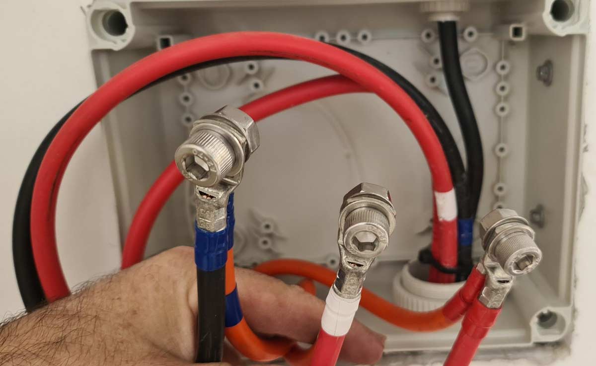
This is what 35mm2 cable looks like (the red and black cables). It’s difficult to work with and stiff like a green tree branch. After a long-distance run, breaking it down to a more manageable size (the orange cables) near its destination is common practice.
Is There An Alternative That Still Uses The Legacy 6mm2 Cable?
If we tweak the sums, assuming a grid voltage of 250V AC, upsize wiring to improve the service cable loss from 1 to 0.4% and use an export limiting device to throttle the solar system at 2kW output, then you’ll squeeze 8 A over 67 m at 1.6% loss.
This may seem like a waste of potential. It certainly isn’t perfect by any means, but many solar systems will spend a lot of hours below 2 kW output. If you can move some loads to the shed, such as a clothes dryer, deep freezer, beer fridge or better still, a home battery or even an electric car, then the system can run these loads without much inefficiency and still push 2 kW back to the house or grid.
An Even Better Alternative: DC Cables
Covering the distance with high-voltage DC is possibly the best answer if you have the right solar design. It will still involve a trench or overhead conduit to carry new cables, and care must be taken to ensure the earthing between the buildings remains compliant and doesn’t generate faults.
High voltage and low current will do the same work as low voltage and high current. The AC side of your system is limited to 250ish volts, but the DC side is legal up to 600 volts. Sadly, conflicting Australian standards prevent us from using 1000 volts, which everything is designed for internationally4.
For a DC circuit, we would normally run a pair of 6mm2 cables for two inverter input channels. So with a spec sheet I have on hand for current generation 415 W solar panels, you could squeeze under the crazy Australian standard 600VDC ceiling, if you have 15 in series for a maximum voltage of 561VDC (depending on temperature correction).
At peak efficiency, these modules are punching out 466 volts at 13.35amps (or 6.22kW) working at 1.4% loss, with an added bonus: no voltage rise problems you could otherwise encounter with the AC grid.
And seeing as you have two inverter inputs, you can have a 12.44 kW system, which would call for cable as fat as your thumb if you tried to manage it with AC wiring.
What If There Are Already Voltage Problems On The Street?
With 30% of Australian premises now having solar connections, there are whole streets in suburbs and states that have little power stations on every roof. The market and power system designed 100 years ago has been completely upended. Where once a hub and spoke network had predictable loads and fairly consistent losses cascading through from generator to consumer, the rise of the prosumer with their own choice means we have democratised energy.
The networks find it difficult though, because thousands of tiny generators behind the meter, pushing the network in reverse at the whim of the sunshine, is harder to manage than a 24-hour cycle with one morning and evening peak. They can use transformers with automatic tap changers to adjust the system voltage according to load. More of those are required now, and they’re working much harder every day.
The other tool networks use is export limiting. They simply put a lid on the power and therefore, the current flowing back from the customers. For many years this has just been a 5 kW ceiling on export at any given time. Hence 5 kW inverters with 6.6 kWp of modules became a thing. In more problematic areas, solar is throttled more, with large and small systems limited to 4 kW or 2 kW or even zero export limits.
So, if you and all your neighbours have solar panels and the grid voltage is very high on a sunny day, you’re entitled to complain to the DNSP (Distributed Network Service Provider). There are national rules they have to comply with, but they’re not always able or very interested in helping, especially if you’re out in the country on a skinny SWER connection with your own little transformer.
Some DNSPs are slow to respond, some view solar power as the problem and impose export limits; making the problem go away without investing in more infrastructure. I am all for making the network deal with the problems. Still, from experience, they aren’t always willing or able to do much, despite many letters written to the Australian Energy Regulator, the minister or local member.
There Is Another Way
Quietly install one of these units and be done with it.
They are only good for 5 kW of voltage-controlled throughput, but I know of people who use them, and they’ve found that quite satisfactory.
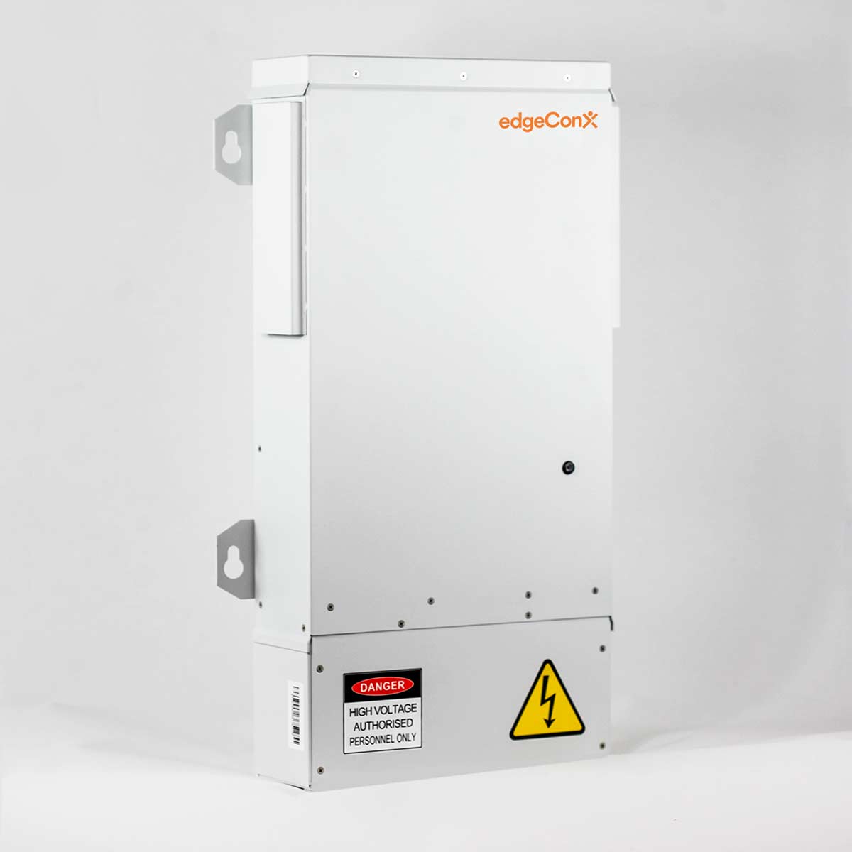
What the machine does is “condition” the incoming supply. You cable it in after the main switch, and the whole place will be fed with a steady 225 volts. Your solar power system will see the same voltage and function as intended, however the line side/network supply voltage will be driven up to whatever is required to make the energy flow back to the network.
There’s nothing illegal about it, and there are no specific prohibitions on this device. You are shifting the problem – possibly making it worse for the neighbours but better for the DNSP. The approach seems to be that if your DNSP no longer hears from you as a squeaky wheel, they aren’t bothered. A bonus is all your appliances will produce less waste heat, work more efficiently, and your bills will fall as a result.
You’ll be wholly unsurprised that the electricity industry doesn’t mind much if the grid voltage is high. It just means they can bill you for more energy.
While high voltage is not as easy to fix as a blocked drain, hopefully you now understand the causes and some solutions to an often ignored part of solar energy.
For Advanced Players Only
Example #1 Measuring loss on an existing system
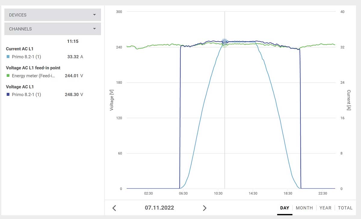
A Fronius Primo 8.2 with its tongue hanging out pushing 33 A. The consumption meter adjacent to the service fuse shows the grid voltage is 244 V. There’s a length of 6 mm2 cable between the inverter and sub-board, then 16 mm2 cable to the main switchboard. 248.3 V – 244 V = 4.3 V being lost along this route, so it just scrapes in at around 1.7% loss.
Example #2 Inverter Shutdown Due To High Voltage On A SWER Line
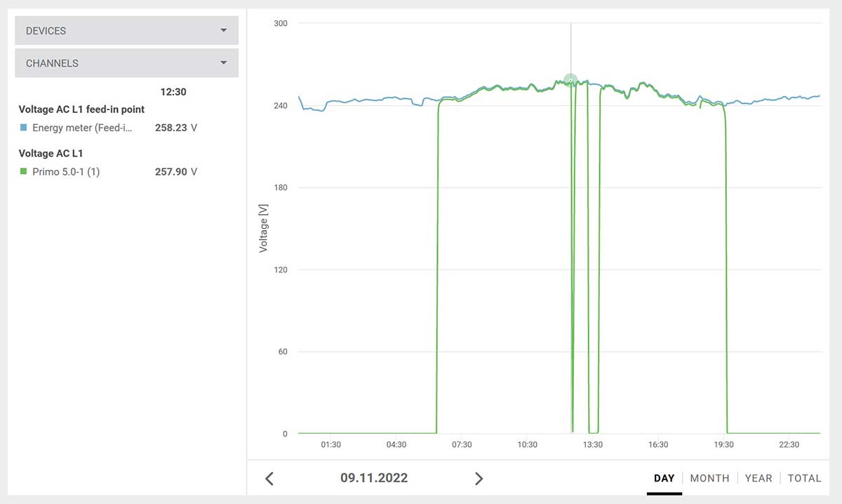
A hard-working SWER transformer. The green line shows the modest export limited system is generating 257.9 V and is about to cut out because other solar systems are driving the grid voltage to 258 volts plus.
Footnotes
- Specifically, the consumer part of the distribution network ↩
- resistive. ↩
- Of course, there’s an app for that. ↩
- It’s a little ironic that the “war of the currents” – were it played out with today’s power handling electronics – might not have been won by GE and Westinghouse, especially as we are now seeing a need for massive DC sources to fast-charge cars. It seems everything that is 120 years old is new again. ↩
 RSS - Posts


The benefit of 3 phase is usually better than simply dividing the current by 3. This is true for the 3 active phase wires. But forgets the benefits on the neutral wire. In at 3 phase setup, there is 3 active wires for each phases, but a common neutral wire. All 3 phases return on the neutral wire. It also needs to be understood that voltage drop is caused by the voltage drop due to the current in each of the active phases + the voltage drop in the neutral phases as it returns. Usually in single phase it will be half the voltage drop in the active and half the voltage drop in the return. But there is an interesting and often overlooked aspect of 3 phase setups that will likely significant reduce the voltage drop on that neutral wire. That is because each phase is 120 degree out of phase, in a completely balanced 3 phase setup, the current returning on the neutral will cancel each other out completely. If there is no current on the neutral, there is no voltage drop. So potentially the voltage drop on a 3 phase setup can be 1/6th the voltage drop on an equivelant sized single phase system in the ideal world. The good news is this benefit applies irrespective of if you have a 3 phase solar inverter, or 3 single phase inverters spread across the phases. Of course the 3 phase inverter should be perfectly balanced and put no current on the neutral. But so would 3 x single phased inverters if they are the same size.
Just a note to alert you to the fact that voltage conditioners can’t be used to overcome this problem, and comply with AS/NZS 4777.2 2020.
See 2.13:
“Voltage at the grid-interactive port shall not be conditioned by an external device such that the voltage measured at the grid-interactive port does not reflect the grid voltage.”
HI Geoff
you are quite correct. In layman’s terms, the voltage being “tipped into” the grid shouldn’t be higher than the AS4777 limits. In order to address this, we calculate the impedence on the mains connection and adjust the voltage regulation to take this into account. This is done by looking at “live” voltage and consumption figures over the first 4 weeks of operation of the device, so we have an accurate assessment of individual household impedence levels on each site.
We can then set the voltage regulation at the maximum level possible for each site without transgressing AS4777 limits.
In most cases we find that the grid isn’t running above AS4777 limits, but its the impedence on the mains connection which is causing the inverter to trip.
if your grid voltages are consistently above AS4777 limits, we can provide this information to the network (or in some cases the ombudsman) to encourage/provide the bais for the network to tap the grid voltages. If, for example, the grid voltages are consistently at 270 volts, we think this is the responsible thing to do.
By keeping the voltages at constant 225V, the Edge IQ also overcomes the volt-var and volt-watt output restrictions which happen when the grid is running at max voltages which are still within AS4777 limits.
The 3 phase Edge IQ (15KW) works on the same basis, but also ensures balanced voltages across each phase, which protets 3 phase equipment (and your savings)
Agreed that is all very clever use of technology.
As you know, AS/NZS 4777.2 disconnection “limits” are much higher than the points at which the Volt-Var and volt-watt response modes kick in.
From a network perspective, because the volt-var and volt-watt response modes are never activated in the inverter due to your device lowering the voltage the inverter ‘sees’ at its grid port, the local network never receives the voltage dampening effects of var absorption, and at the higher voltage end, generation reduction.
Your device has effectively obfuscated your responsibility to comply with AS/NZS4777.2 2020, and help stabilize grid voltage with increasing PV penetration.
It’s a very clever work around, but it prevents the inverter system operating in the way AS/NZS4777.2 intended.
(I’m on the committee that wrote it).
I guess it comes down to the question of who is responsible for the grid voltages.
I would argue that the network has way more tools at its disposal to manage voltages than the customer. Using volt-var and volt-watt should not be the main network tool. Networks should have to report and be held to account over the voltage and power quality levels they provide. They are not, which is completely unfair when those same voltage and power quality levels are causing customer investments to under perform.
I am not sure how many customers understand the technical reasons behind the volt-var and volt-watt approach. I am certain that most customers have no idea about how networks are able to restrict and curtail their solar operations in this way. I am equally certain that networks do not publish reports on localised (or network wide) voltage levels, which they should do given it can have a significant impact on the financial performance of your solar investment.
HI Geoff
you are quite correct. In layman’s terms, the voltage being “tipped into” the grid shouldn’t be higher than the AS4777 limits. In order to address this, we calculate the impedence on the mains connection and adjust the voltage regulation to take this into account. This is done by looking at “live” voltage and consumption figures over the first 4 weeks of operation of the device, so we have an accurate assessment of individual household impedence levels on each site.
We can then set the voltage regulation at the maximum level possible for each site without transgressing AS4777 limits.
In most cases we find that the grid isn’t running above AS4777 limits, but its the impedence on the mains connection which is causing the inverter to trip.
if your grid voltages are consistently above AS4777 limits, we can provide this information to the network (or in some cases the ombudsman) to encourage/provide the bais for the network to tap the grid voltages. If, for example, the grid voltages are consistently at 270 volts, we think this is the responsible thing to do.
By keeping the voltages at constant 225V, the Edge IQ also overcomes the volt-var and volt-watt output restrictions which happen when the grid is running at max voltages which are still within AS4777 limits.
The 3 phase Edge IQ (15KW) works on the same basis, but also ensures balanced voltages across each phase, which protects 3 phase equipment (and your savings)
I live on a rural block. I have had problems with Inverter voltage rise. My system is 2 phase 180 degrees, with a 35mm service (2 Line + 1 Neutral cables). I have my inverter set to voltage limit. This actually helps my neighbors (4 others on this transformer) because I do not push the voltage up.
Before, my inverters reset periodically, then took abt 90s to reset. Now my total feed current is limited, but I actually export more (due to no resets). Also
because I run lower voltage export, my neighbors inverters hopefully will not reset as often.
I will put a secondary dwelling on my block, abt 100M from the metering point (abt 130M from Transformer). This will use 70M of 16mm sq cable, but I will have a zero export solar system & at least 10Kw of battery. Really, the house will virtually run off-grid, with Grid backup.
Sounds like a very reliable system that’s cheaper to run than servicing a diesel generator on a remote area system.
Cheers
You cable it in after the main switch, and the whole place will be fed with a steady 225 volts. Your solar power system will see the same voltage and function as intended, however the line side/network supply voltage will be driven up to whatever is required to make the energy flow back to the network.
Im a bit confused here. Does this mean the appliances in my house would only get 225 volts? Not say 235 or 240? Does this suit say my induction cook top , my water pump ?
And I assume it cranks up the grid export side higher maybe 255 or more to get solar credits ?
We initially set the voltage regulator at 230V standard. That can be adjusted according to the customer requirments, and can go to 220V if you wish, which would give you more savings. However, due to impedences and voltage drop within the property – such as a 67M line to the shed – you may need to run the overall voltage at 230V. All your appliances will work perfectly well at the 225-230V level.
Over time, high voltages will reduce appliance life and performance. The Edge IQ also contains ongoing surge protection for the home.
Hi Peter,
If you read through the comments here Richard does a better job of explaining it than I do, but in a nutshell yes, your appliances will behave better at 230V
Cheers
I got to say I am dubious of the consiratorialy suggestions that DNSPs like high voltage “because they make more money” claims. I am also a bit dubious at the “Instantly reduces your power consumption by up to 10%” and “Increases the yield from your solar panels by up to 15%” probably only saved from a false advertising claim by the fact that they put the work “up to” in the claim. I suspect if you looked at real world loads, and real world use cases and performance and factered in the efficiency loses of devices of this type etc, I suspect most people expecting to see these claims pay out closer to the higher end, might be a little disappointed. Like all of these claims, there are some real things that are used to support these assertions. eg for purely resistive loads (incandesant light bulbs, traditional electric stoves and HWS and your kettles and bar heaters etc), for sure, increasing voltage will increase the instantainious power draw. But your kettle boiling quicker and turning off quicker and in theory this will use the same power. Sure, you 100W incandesant light will use a little more than 100W, and probably most people will have them on for the same time, so they will use more power. But they will burn brigther, and maybe that will be offset by needing to run less lights. And yes, more instantanious current for these loads will cause more losses in the wires leading to the appliance due to ohms/power laws. But some of this will be clawed back with shorter run times. What is not clawed back would be relatively small and probably very much counted by the benefits of LOWER current for a lot of other loads. A lot of inductive loads require a fixed power output and increasing voltage will reduce the current to provide the fixed power. So in this case, increasing voltage, reduces current and thus losses in all your wires etc.
There are swings and roundabouts. But I suspect these sorts of claims get more airtime than they deserve.
Hey Matthew
I get your point about false claims – the industry is rife with them.
As far as Conservation Voltage Reduction (CVR) is concerned, there is a fair amount of work already done. Electricity NorthWest in the UK has done the most extensive customer based research, which supports their dynamic voltage control program. Their claims support a 1.3X CVR, but we think that is more inluenced by commercial and industrial load types. At a residential level we see 0.9 as the more realistic CVR factor.
As far as solar savings are concerned, it depends on the starting grid voltages. In some cases we have customers who have been locked out 100% of the time. Others lose out to volt-var and watt value erosion. Generally, if you are in the high 248-253V range you will see that 10-15% overall saving from improved solar and beter CVR. The Energy Security Board study in 2019 (which used a lot of Solar Analytics data) showed average voltages nationally were over 247V, so that’s quite a few people.
The final area of value is in appliance life and protection. The ongoing surge protection has tangible value when compared with the single event protection you can put in the switchboard. But also there have been good studies by UNSW on the deterioration in electrical equipement life caused by high voltages. Once again, this will depend on the type of equipment, but I think most people can relate to the potential impact of poor power quality and voltage spikes on appliance life.
Excuse my ignorance in this area, but what is a 1.3X CVR mean and how does that compare with you 0.9 figure? Does that mean commerical and industrial benefit from higher voltages?
As for as the solar savings go, while I can see some corner cases where your device might help. eg someone has a shed a long way from the main grid connection point, you dropping the voltage down allows the inverter to not be affected by the voltage rise on that part of the link. But this is not actually a grid voltage too high issue and the rise on the actual main grid connection. It is an issue with voltage rise on the actual property. But I suspect this is a bit of a corner case, and I assume most people have their solar closer to the point of interconnect and there is less benefit there. But irrespective of this, how do you comply with AS/NZS4777.2 2020 when you see voltages at the thresholds on the grid side. I assume you would have to address this to comply with the regulations. If this is the case, I assume the only solution is to throttle the power you are exporting which is exactly what the solar inverter would do?? In which case, where are the savings?
Seems to me in most instances, you can’t have your cake and eat it too. Either you comply with AS/NZS4777.2 2020 when you hit the threshold, or you are not complient??? Am I missing something.
Hey Matthew
Conservation Voltage Reduction (CVR) is the calculation of the relationship of consumption vs. voltage. There are lots of studies from various international sources if you Google it.
A CVR factor of 1.3 means that for every 10% change in voltage there is a 13% change in consumption.
Lots of VR companies use claims like this. Our experience is that the CVR factor is very subject to load type (resistive load for example doesn’t have such a high CVR) and that the 0.9 CVR claim is more conservative. You’ll get these savings whether you have solar or not, especially if you have inductive loads on timers for example
On the solar production side we are simply optimising your inverter output so it operates as if “seeing” a 230v. Of course, when the network runs the voltages at super high levels like SAPN did last week, we have to curtail your export, but there is a lot of value to be had between 230v and 255v. Are we avoiding volt-Var and volt – watt? I’d say we are ensuring the customer receives voltage at the recommended safe and reliable level
Going back to SAPN….last week we saw they ran voltages at up to 270V in places in order generate more load (see CVR) and curtail your solar. This is a terrible precedent which means any network company can do the same whenever they deem fit. Remember the references to “safe and reliable”???
I find the voices against voltage regulation solutions for individual customers truly bizarre at a time when the networks cannot control voltage and are happy to run voltages beyond regulation safety and reliability levels when it’s convenient for them.
Interestingly when we raised this with the AER they said it was a state level issue. When we raised it with the states they said it was an AEMO issue. And then AEMO pointed us back to the AER…
Great blog post, really interesting! Thank you Anthony!
No worries Tom,
I actually learn a good deal from the comments too, it’s fascinating when we get these people together.
Cheers
good article.
I would have thought 225V to appliances would be a bit marginal with swich mode power supplies in some devices
Agreed. 230V is generally recommended, but you can request this to be changed (up or down) whenever you wish.
“They are only good for 5 kW of voltage-controlled throughput, but I know of people who use them, and they’ve found that quite satisfactory.”
Does this mean if I have 10Kw of solar this will be no good ?
My down lights keep failing every 3 years., is this a sign of voltage issues. They are the top of the range cliplsal
HI Chris
Sounds like you do have a voltage issue. Your solar should show this, but if not you can check your voltage over the course of the day with one of the EdgeConX voltage readers – they are on the website.
We do have alternatives for larger solar systems, including a 3 phase solution. If you contact us on the website we can see what might work for your circumstances
Richard
I installed 5kW/6.6kWp solar system on my shed and had to upgrade the feed line from the house’s main switchboard from 6mm² to 10mm² cores for this exact reason. Having done this, the shed is now ready to also handle an EV car charger, so it’s not a bad result!
There is a 3rd rule number for plumbers:
3) Don’t bite your nails……
Makes sense when you think about it 😉
Hello!
Thank you for explaining this.
However, I still don’t understand how voltage raise and drop are terms.
After reading you analogy of going to a pub I see the point, but I don’t see how that is set in terms of a PV system.
I am confused when the terms are used.
For instance If I look at enphase microinverters they say that vraise is the right term since it is a generation source, but if I look into other resources they talk about a vdrop since the voltage travels form the source (PV system) to the point of connnection (J Box, combiner box etc).
At the beginning I thought vraise was applied only for micro inverters and AC voltage, and vdrop applies to the input side of an inverter (DC voltage).
But it seems it is not the case since I found at NABCEP handbook that voltage drop applies for AC and DC voltage
If I read the statemetns of why we should call it vdrop makes sense (Since the voltage is traveling throu wire, the voltage drops bc of the recistance of the wire), but if I read the statement of why we should call it vraise ( since it is a power of source and the voltage accumulates at the end of the terminals) that makes sense too.
As a final definition I read that voltage drop is applied for voltage from utility to load and voltage raise is from source to utility.
Going back to the analogy of the pub, if in my installation I measure voltage of 300 DC voltage at the j box an then I take the measure of voltage at the inverter terminals, I can see that the voltage drops to 298 (.68% of drop) how that drop can be taken as a raise?
Thank you in advance for reading this comment and for the explanation!