
If your inverter sees a grid voltage that is too high for too long, Australian Standards mandate it disconnects from the grid. Before the voltage is so high it disconnects, your inverter may also reduce its power output in response to high grid voltages.
There’s a lot of fear-mongering about how the rise of renewables threatens our power grids, but a real problem getting real attention from the industry is how voltage rises on our mostly old and inflexible infrastructure stops customers from getting the most out of their solar PV installations.
Anyone who’s trained in this stuff already knows this of course, but I’d guess most consumers don’t realise the relationship between the voltage at the inverter and the voltage on the grid is very important. When things go wrong, the customer gets a bill showing far less electricity shipped to the grid than they expected, and someone – a solar installer, an electricity retailer, or a network – gets an angry phone call.
At a recent Clean Energy Council webinar, all four speakers – the CEC’s James Patterson, Solar Analytics’ Stefan Jarnason, SA Power Networks’ Travis Kausche, and SMA’s Piers Morton – agreed over-voltage problems are a big contributor to consumer complaints that they’re not getting value-for-money out of their grid-connected solar power systems.
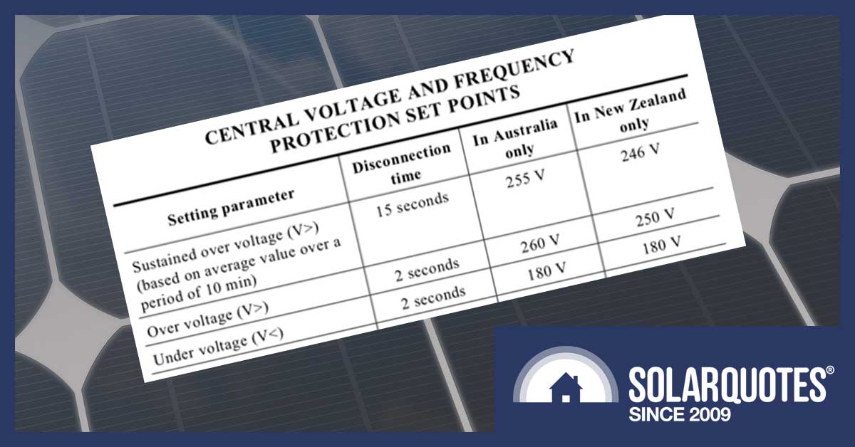
The inverter has to be running at a higher voltage than the grid, so it can push power out (current flows from a point of higher voltage towards a point of lower voltage, never the other way around). The problem is every solar installation pushing power into the system lifts the network voltage just a little – and with tens of thousands of systems coming online on SA Power’s network each year, some systems are confronted with a grid with voltage outside inverter tolerance (the AS/NZS 4777.1 standard limits inverter voltage to 255V).
It’s worth noting solar power systems aren’t the only cause of overvoltage issues – as Solar Analytics founder Stefan Jarnason remarked, enough overvoltage issues occur at night-time to prove that.
SA Power Networks strategist Travis Kausche told the webinar the state currently has homes feeding 1 GW into the grid; 163 MW of that came online in 2018, and there’s up to 300 MW in the pipeline for 2019.
Kausche said the growth of solar energy “makes the dynamic range [the difference between the highest and lowest voltages seen on the network – Editor] much greater than if there was only load on the network”.
What happens when the inverter has to back off? The customer starts complaining, usually to their installer, that network feed-in tariff payments are falling short of their expectations.
Everybody can do the right thing, but the system doesn’t work right (Image: Clean Energy Council seminar)
That can be fixed, but it’s always better to try and avoid problems than to have to rescue the relationship with a cranky customer – and preventative measures, as well as remediation, were the focus of the webinar.
Scaling The Overvoltage Problem
Solar Analytics’ Stefan Jarnason said his company’s analysis of 30,000 customers showed 50 percent of feeders had overvoltage issues 50 times a year or more, when scanned for voltages exceeding 253V for more than 5 minutes (undervoltage was, by comparison, rare, affecting only 2 percent of customers experiencing 50 or more events a year).
The more granular the data-logging, Jarnason showed, the easier to see the impact on the customer. Solar Analytics’ capture at five-second resolution clearly shows an inverter shutting down because its voltage is too high, trying to reconnect, shutting down again, and so on.
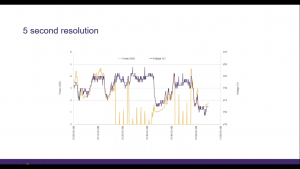
The orange line shows a system shutting down because of voltage rise on the grid, then trying to restart (Image: Clean Energy Council seminar)
Fixing The Problem
The challenge for networks is some of the available fixes are hard to implement on old infrastructure.
Imagine a long feeder serving many customers, meaning that to maintain voltage in-tolerance for the last customer, the voltage closest to the transformer will leave the inverter very little headroom.
As Kausche explained, the network provider can only adjust the voltage by changing the tap on the transformer if the transformer is new enough and has lower voltage taps available – but the majority of SA Power Network’s 70,000 low voltage transformers don’t have that capacity, and transformer upgrades are expensive. Substation transformers are much more capable, but don’t offer granular voltage management.
“We have these legacy old assets that can’t really go down,” Kausche said.
The webinar highlighted the role solar installers can play in remediation, with all three speakers saying that getting inverter installation and configuration right plays a big part in avoiding complaints.
SA Power Networks has changed its inverter rules to require all inverters installed on its network have the Volt-VAR setting enabled (listed as optional in the AS/ NZS 4777.1 standard), so the inverter is more responsive to network conditions.
The network is also working with other providers to produce a standard set of solar inverter settings, so at some point OEMs and solar installers have a standard configuration profile Australia-wide.
SA Power Networks is also trying to move more customer loads to the middle of the day. If an off-peak hot water system, for example, can be remotely configured, adjustment is easy, and from 2020 there will be a “sponge” tariff to encourage consumers to schedule loads such as washers, dishwashers and pool pumps towards the middle of the day.
What Solar Installers Can Do
The CEC’s Patterson pointed out system design, including cable gauge, is also important to manage voltage rise. The CEC surveyed participants to see if they liked the idea of an online calculator tool to help installers design their solar power systems – and received a 100 percent “Yes” vote; so we can probably expect to see that offered fairly soon.
SMA’s Piers Morton said the impact of voltage rise emphasised the need for remotely-manageable solar inverters, something SMA will be introducing in the near future, and said installers can also help by paying more attention to balancing systems across different phases.
If you are solar power system owner with a voltage rise problem Finn has written a handy troubleshooting guide here.
 RSS - Posts


I had constant dis-connects in summer when my system was installed. You could literally see the voltage rising fast as cloud cover went into a break, then bang, dis-connect. Only to re connect maybe a minute later.
The supplier remotely upped the disconnect voltage a bit above 253v and no issues since.
Same thing happened here to me in Mexico. My installer tweaked the disconnect voltage and no problems since. The learning curve is pretty steep with solar for sure.
Thanks mike.
My street has more than 25% solar.
I also tried calling the power company. They sent a guy out in the evening and said all is in spec!
At that point it was easier to get my supplier to fix it. Never had a problem since. More than a year now.
I work in the garage where the inverter is mounted so i was very aware of it dropping out. Must be many solar owners who will never know.
253.?
235 is the target
Approved imported appliances are all new international standard .100 to 240 volt no plus or minus required according to the SaaS electrical standards mob
253 v any warranty will be denied due to heat damage caused by high voltage . Anything above 245 v appears to overheat these appliances and dramatically shorten life span .it’s amazing the morons in charge have allowed this to happen .
It’s a serious safety risk what they should have done was lower the local grid voltage by installing appropriate transformer infrastructure able to cope with solar feedback.
The higher the voltage the less you can send back and your inverter will not like the constant high voltage either .
Bastards really are peanuts .
As a result your solar output will drop , they are likely limiting you as well and choking your feedback .
And increasing your bill because your appliances can do nothing with the extra voltage but shunt it around as heat dramatically shortening life span ….
They did you no favours at all. In fact skrwd you a bit harder …….
I got the bastards to put up new connection line to pole as the old one was thin crap causing higher voltage rise.
I got down to 251 max but all day long .
Still a long way off 235 our alleged grid voltage and far beyond new appliances capabilitys.
Most new appliances have a small wire which burns out under high voltage heat which usually prevents house fires but if the wire doesn’t burn out for some reason ignites something in the board you will have a fire caused directly by high voltage not a failed device . The safety device might have failed but that would not have been an issue if voltage was 235 v…..
Liability disaster just most sparky will not go up against a corporate and you are left arguing app by yourself against billion dollar corporation who knows they can get away with murder , should anyone’s house incinerate them …imo
We need action .
240 hard cap . Distributers . If they can’t ,renationalise .
Hi Dean,
Here in the UK our voltage standards appear to be the same as Australia. I had the same problems with my grid supply. When we moved here, the RAF base had shut down. Years later they reopened it, then our grid problems started, most mornings around 7;00 the breakers would drop out, reconnecting them for 3 to 5 minutes they drop out again. This continues for about 1 to 1 1/2 hours. Some evenings the same. My voltmeter showed 263V at cut out. Recording voltages over a week showed the grid voltage mean at 245V. This has 2 consequences, first the safety to over voltage spikes is reduced by 15V, leaving 8V for spikes. Second, as electricity is priced in kWh, it means that you are paying over the odds for electricity, since kW = V x Amps, increase the Volts increases the kW to no advantage to the consumer and more money to the power companies.
It’s worthwhile now to repost my earlier post on this subject from Aug 2020:-
The standard range of power quality issues have been touched on.
(Voltage Transient – Sag – Swell – Under Voltage – Interruption – Steady State Distortion – Flicker and Noise).
All inconvenient to some degree for sure, but the elephant in the room not yet mentioned, but one which will cost On-Grid customers cash, and likely to come into force anytime soon, will be a Grid Power Factor penalty rate (PFR).
Advanced functionality grid tie inverters will need to respond to this requirement in design through functioning in a way that will maximise savings across all areas including managing active power and reactive power thus power factor. The further away from PF equall to 1 then the greater the reactive power penalty rate will be.
The grid authority will also have the power to direct inverters inject reactive power to bring power factor into line. Already a common practice elsewhere.
So there it is power factor is king in any generation system servicing loads. Every power equation in AC theory includes the value V (Voltage) including Power Factor PF. As we already know current I is inversely proportional to the PF, therefore if PF is low (less than 1) the current will increase. I is proportional to 1 divided by PF. Resulting in increased I squared R line losses, and lower efficiency of the system. IE higher electricity bills for lower Active Power usage.
Learn about Power Factor. It is the governing electrical concept for all Generation Systems including Roof top Solar inverter Systems. It alone can bring the Solar PV roof top industry to a standstill.
I was having these discussions with Ergon and Energex over 10 years ago representing several Chinese Inverter manufacturers.
PS. Greater conductor sizing to transmit the same quantity of power is not a sustainable solution.
Lawrence Coomber
….sort of ‘Stone Soup’ in reverse.
I asked long ago whether there were any whiz-kids out there that could modify a gee-whiz grid-connect inverter so that it would run a stand-alone operation?
Acquired smattering of what would be involved, but found nobody who’d try it on. (The suggestion that a battery connected inverter hooked into the ‘grid-input’ might work. ) Is that workable?
“The inverter has to be running at a higher voltage than the grid, so it can push power out (current flows from a point of higher voltage towards a point of lower voltage, never the other way around). ”
Well if we had a DC grid the above would be true. But for AC a tad more complicated. Simply increasing voltage could in fact do nothing to increase power flow. What we need to do is in fact try and increase frequency at the inverter. But eventually when we get the power out of the inverter first principles will see a voltage rise
No. It is not an more complicated. Just as in DC, AC also will only flow from high voltage to low voltage…full stop end of story. The size of the voltage difference and the impedance of the link directly dictates the amount of power that flows (or probably more correctly, the amount of power that the inverter wants to put out and the impedance of the link determines the voltage that the inverter needs to apply to export that much power). And this is why voltage “rise” is the problem, because it is often this rise that triggers the voltage porblem in the inverter, ever when in some cases the voltage at the point of connection to the grid might be in spec, and why installers should be doing voltage rise calculations and keeping that in spec by increasing the size of the wires to the house when needed. Frequency does not come into the equations anywhere.
I think you adding 1 and 1 together and coming up with 11 when you bring up frequency. Yes, frequency is important in the management of the grid. Usually when there is an oversupply of power into the network, the frequency will tend to rise, and when there is a lack of supply, it will tend to fall. And this mechanism is used in inverters to throttle supply when things get out of range, This “inertia” from spinning power generators helped keep things in balance. But it has nothing to do with the flow of power. Our grid tied inverters (and all generators on the grid) in fact have to actually match the frequency of the grid as it fluctuates.
Not quite. Changing the voltage on an AC generating device changes the reactive power power output. And that can be either to the generating device or from it. It is the method by which reactive power is controlled from all generators including inverters . And for those states where power is required to be delivered at 0.8PF lagging (from memory) it done by varying the voltage. Wwhich makes the VD problem a lot worse as this any change from unity PF increases current flow and hence more VD.
Real power flows are increased by ‘trying’ to increase frequency. On a conventional generator this is from opening control valves. On a grid tie inverter it is a pile of electronics.
Sorry, to me that looks like adding 1 and 1 and 1 and 1 together to come up with 1111 and in my mind and further confusing what is a comparatively simple issue with half truths. While clearly you have some understandings behind some things, but to me it seems like a case of misinterpreting what you have learned. To me your logical seems to be flawed, probably too much to go into here. BUT you speak with great authority, and if this is backed by real knowledge and experience, I am always keen to be educated by those that might know something that I don’t rather than risk continuing to live in a world of ignorance in the off chance I am wrong. And maybe the accepted laws of physicals have changed and you can educate me about some new development that has changed everything. After all, my Electrical Engineering degree was 30 years ago, and in truth since I have not worked in building generators or inverters, and don’t pretend to be an expert in grid transmission or generation so it is not my area of expertise. But I do have a reasonable understanding of things and probably more importantly base principles that tend to drive this. But maybe there has been fundamental changes which makes a large part of the fundamental principles wrong (possible by unlikely)…..or more likely I was too drunk and did not go to that lecture so happy to be corrected if that is the case.
But the realities is that the laws of physicals, and flow of electricity and power flow do not pander to a bunch of self appoint experts on the internet speculating about it (including myself in that). They are governed by tried and tested mathematical principles. So if what you say is true, can you point to any documentation or equations that support what you are saying, so I can educate myself.
The whole AC is more complicated than DC is really half true. But reality if you look at any period short enough, it is exactly the same and we probably don’t need to confuse anyone sort of an electrical engineer with the complexities. Only difference that does make it a bit more difficult is that capacitance and inductance does introduce some factors that can mean we need to take these into account and this means that voltage and current is always changing and not necessarily in sync with each other as they would be in a static DC circuit (or more correctly they are in sync with each other, but can be phase shifted so current lags or leads voltage which can affect PF). But they don’t fundamentally change the simple principle that power ALWAYS flows from high voltage to low voltage, and as long as 2 AC sources are in voltage sync as they are required to be in the grid, voltage will always flow from the high to the low voltage source. Full stop, end of story. Noone needs to read on from here, unless you are not convinced of this VERY simple principle.
To support what I an saving I only have to point to ohms law and power equations which exactly predict voltage rise and fall on any connection. Most people will know of ohms law as I = V/R. ie assuming constant resistance, we can see that current is directly proportional to voltage drop/rise. Sure, AC DOES make a things a little more complicated deep under the covers because of constantly changing and not always in phase values for I and V. And also because any transmission like will usually have some element of capacitance and inductance, so we need to adjust ohms law to the one that is applicable for for AC circuits. This is almost the identical I = V/Z where Z is impedance measured in you guessed in ohms!! So again, we can see a direct relationship of current to voltage for any particular impedance that can be used to calculate the voltage rise or fall. Notice there is no frequency in this!! But wait I hear you say, because you know enough stuff to be dangerous. Impedance IS affected by frequency if there is any element of inductance or capacitance on the circuit. This is because you know that 2 of the 3 components that make up impedance is because of capacitance and inductance of the circuit. And both capacitance and inductance are directly and proportionally affected by frequency as any 1st year student knows (inductance is proportional and capacitance is inversely proportional). Added to that practically all AC transmission lines will have elements of both inductance and capacitance by their very nature. But this relationship for a transmission line is small because the impedance is made up of inductance, capacitance and resistance of the wire, and the resistance of the wire is I suspect the most significant factor and not affected by frequency. In addition, even if we incorrectly assumed all the impedance was due to inductance and capacitance, in the grid the frequency changes are relatively small proportionately which will also limit their impact. Where I am live, the last 24 hours the fluctuation has been less than 0.4% (despite my generation swinging between 0 and 14kW). NEM I think targets is 6% and things would be going pretty wrong when these events happen and should be very rare. So you can see, in the extreme, the difference might make to I = V/Z is bugger all in the normal operation in the grid and can probably for all intensive purposes, can be ignored. Its impact is a very small % of a very small % making it pretty insignificant. Now we also have the power equations of P = IV. Again, notice, no frequency in this calculation. So if we assume frequency plays a trivial roll in practical power transmission impedance as outline, and if we put these 2 equations together, the ONLY way we can increase output from a power station is to raise the voltage. From ohms law, we can see if we do that, we will output a greater current. And we can see from the power laws those things equate to more power. Notice, while it is hard to say frequency plays no part in this, for the purposes of this discussion it is a small enough part to be ignored, and probably not worth raising it and potentially distracting people from the real drivers.
The whole reactive power / power factor is largely irrelevant. Reactive power is really just a side effective of voltage and current being out of sync, and this does affect the P=IV equation, as you can see different values of VA and W if PF is not 1. But this is a side effect of the inductive load that a is typical of a spinning generator (and other generators and loads), and NOT a requirement. In fact if you want you can correct power factor by adjusting with additional capacitors and inductors to correct PF to 1. This does not impact on the generators ability to output power. But for the purpose of this practical discussion I can’t see any reason it would allow power to flow from low voltage to high voltage which seemed to be the thing you were suggesting could happen and the reason I commented in the beginning.
As for broad statements that “Changing the voltage on an AC generating device changes the reactive power power output” I would love to understand what you are really saying here, and if it is what I think, where you get that idea from or what relevance it has??? Sure all sorts of generators and loads might have a power factor of less than one because of their own unique capacitive / inductive characteristics, but in truth this can all be corrected if required. And in fact, I could be wrong, but I believe your typical grid tied inverter can also output with a PF of effectively 1 or something else if that is what the distributor demands for their own reasons. As a case in point, my grid tied inverter is putting out power with a PF of 1 or close enough to it to not matter. I know this because not only because that is what the grid profile tells me, but now I think of it, I have also measured it (I get the same output from a monitor that does not correct for PF and one that does which shows in it 1). If what you are saying is true, I could never export any power which is not the case.
I think you are getting confused with inertia, and have probably heard of its traditional importance in stabilising grid frequencies. ie when there is sudden drop in supply this inertia can supply the grid for a brief period of time (accompanied by a frequency drop), or if there is a drop in demand, the spinning generators can absorb the excess to turn it into inertia (and a side effect of this will be a small increase in frequency). But AEMO and the generators are working hard behind the scenes to prevent this ever happening and in the perfect world the grid frequency would always be 50Hz at all output levels and at all times. But this does NOT mean that frequency is the mechanism that real power is pushed to the grid. Surely if frequency was required to push power to the grid, we would see high frequency in the middle of the day on the grid when power stations are outputting at maximum load, and low frequencies in the middle of the night off peak times when there is less generation on the grid. But this does not happen!!
I think you need to consider “grid inertia” like a manual car travelling down the highway with the cruise control set at 100km/h. Think of the car like the power station, think of the engine RPM as the frequency of the grid, and think of the hills the change in the load that is required on the grid, and power that the engine puts out as equivalent of the power that the power station needs to produce. In just like the grid with its spinning generators, the car has inertia from the mass of the car moving at 100km/h and interia of the spinning engine. In this scenario, to stick to 100km/h, the engine RPM will be a particular value (lets stay 3000rpm for arguments sake and notice I have said manual car because unlike automatics most people would be aware of there is a fixed relationship between RPM and the speed of the car assuming the same gearing). When we hit a hill, to maintain the 100km/h (50Hz), the cruise control will need to inject more fuel so the engine generate more power (same as power output from the power station in this analogy) to maintain the 100km/h / 3000rpm. We are clearly producing more power, but note there is NO increase in RPM. If the engine is powerful enough and cruise control reacts fast enough and with the added benefit of the inertia, you will stay at exactly 100km/h / 3000rpm. Opposite happens when you go down the hill, still 100km/h, but less power needed so less fuel to the engine, less power is produced by the engine, but still 100km/h and still 3000rpm. In fact you will be able to travel along on your merry way at exactly 100km/h and 3000rpm despite that you might be varying power all the way from zero (coasting down a hill) to 100% for a hill that you have just a powerful enough engine to maintain 100km/h / 3000rpm, That will happen indefinitely until 1 of 2 things happens. 1 is big long steep up hill that your engine is not powerful enough to maintain 100km/h / 3000rpm or same downhill (think in the grid of demand increase above the capacity of the generator), which even with zero power from the engine causes you to accelerate past 100km/h / 3000rpm. Lets focus on up hill. Now if the hill is steep enough to slow you down, but only short, your inertia carries you over that hill, without you even noticing any significant drop. But this inertia is effectively a conversion of some potential energy into actual energy, but you do loose some potential energy / inertia you will need to provide power to regain (shows up as a small reduction in RPM). But if the hill is longer, pretty soon, your speed and RPM will drop because you just don’t have enough power and if not addressed and the hill goes on, the car will slow until it all stalls because you have run out of power (Assuming you don’t change down a gear in the car, which is the answer in the car because you would prefer to get up the hill slowly than not at all, but this is not an option in a power station that helps the grid, because while change down a gear might increase torque, it does not increase power, so in your power station, it might help you maintain frequency, but not power output which is the important thing for a power station in times of limited supply). Same happens in the grid, the frequency drops. But it is not the drop in frequency that is the real problem. The problem is that the generator is now not spinning as fast, and that means less power and struggling to maintain voltage high enough for demanded power. As per equations above, lower voltage becomes lower power, and suddenly unless you can rapidly introduce more generation, or reduce loads, the whole system collapses, and this is what causes the blackouts (planned to protect the system, or unplanned that takes everything out).
Now I hear you say that this is evidence to proovde your point, because the car engine is trying to rev at higher RPM and this is what is producing the power. But that is putting the cart before the horse. And as can be seen from above, in most cases the power output can be varied from 0 to 100 without changing the RPM/Hz. You are pointing of the side effect that does not actually happen most of the time, and making it the cause. Reality is much simpler in a power station. They are built and are required to maintain frequency, not increase it, or decrease it. They push power power out by rising the voltage. On our end, it is exactly the same and practically nothing to do with frequency.
Additionally, if it was frequency that was needed to push power through the grid, and not voltage, surely we would see the frequency drop as we move through the grid from the generators. This does not happen, it is voltage drop we see, with the frequency largely the same.
Finally, your original comment that I felt needed correcting was “Simply increasing voltage could in fact do nothing to increase power flow”, I guess if you could give me 1 real life example in the grid were this could be practically true. Example needs to be 1 where power can flow from low voltage to high voltage in a real life grid where everything is in sync.
Now maybe I am missing something fundamental, and if so my apologies and I would really value being educated. If so, suggest you point me at the reference or calculations to the support your claims.
Too much electro-wank here!
This is all way beyond the capacity and interest of any but the most dedicated solarist.
Tone it down,please. This discussion should be taken offline where you electro-donks can indulge to your hearts’ content.
Richard I’ve not actually read Mathews post so can’t comment on it. If it’s too complicated for you then maybe you are in the wrong place. There are many here that have views and the conversation may get somewhat technical as many of us are engineers of various degrees and want to have some input by putting their views forward.
Matthew, I think you’re confusing current flow with power flow. In DC systems, both are always in the same direction, but this is not true for AC systems. You can have the current flowing in one direction and the power flowing in the other direction.
In a standard 50 Hz grid with a source and a load, the current flow direction changes 50 times per second, the power flow, however, is always in the same direction. That’s why I tend to agree with Peter, but I would like him to develop his line of thought.
Jeez Esdras – I think you might be trying to teach Matthew to “suck eggs”. I will agree that Matthew’s “missives’ are so long, that by the time I get to the end, I may have forgotten the beginning – but I do believe he understands the principles of AC theory.
Please realise that the voltage also changes polarity 50 times a second.
So, for a purely resistive load both the current, AND the voltage change dirrections at 50 Hz, so the power is always positive.
However, what you have said is not always true. If the load is other than purely resistive, at some points in the cycle the current and voltage will have opposing polarities – and the power flow will be negative (the load will be supplying power back to the load). The amount will depend on the “power factor”.)
This is not rocket science – the lower the power factor, the greater the current flow, for a given nett power delivered.
This is why DNSPs want PF close to 1 – as otherwise they lose the additional i2R losse in distribution – which they cannot charge you for.
I think the graphic CEC is missing a 2 in front of the = 58v which should be = 258v unless I am missing something.
Well spotted. Fixed. Thank you.
Richard,
Solar Edge inverters can be voltage limited instead of power limited. My system automatically winds back to control the voltage, so I actually help my neighbors too. My best export was 85Kw/day last christmas. (14Kw panels, 2x 5Kw Solar edge inverters. Replacement legacy system.)
On my system, the calculations said 8.4Kw, but by using Voltage limit, I can sometimes approach 9Kw (depending on what my neighbors are exporting).
regards,
Doug,
I think when you say “voltage limited” you are referring to “volt-watt mode” which is an optional mode in AS4777.2:2015 that pretty much all the mainstream inverter manufacturers implement. You can read about it here :-
https://www.gses.com.au/wp-content/uploads/2016/09/GC_AU8-2_4777-2016-updates.pdf
Effectively, if enabled, instead of the inverter doing a hard shutdown when various voltages limits are reached, this mode allows for slightly higher voltage limits. But the trade off is that you will ramp down output, and in fact the ramping down of power starts at a lower voltage.
Overall, this is better for stability of the grid, as it enables a mechanism where output is reduce when there is oversupply, and also avoids some big swings in power if big groups of inverters where all going from full power to shutdown at the same time. But for us end users there is some upsides and downsides. The upsides is that it typically raises the bar for the voltage that the invester actually full shuts down. This is further helped by the fact that when you ramp down, you reduce the current and this also reduces the voltage rise that you are creating by generating power and trying to push up, so there is effectively a double benefit here if you only cared about preventing inverter shutdown. So for anyone who implements this, there is likely to be a significant improvement in the numbers of shutdowns if their voltages are fluctuating around the limits.
But, the downside is that the trade off for this, is that voltage limits which you must ramp down are lower than the trip voltages. So while you might trip off substantially less, you are going to be spending more time throttling your output and that throttling will be starting at a lower voltage. This means you will be spending time throttling your power, where under the standard mode, you would have been able to output 100%. For for some people implementing this, it will actually reduce their overall output if their typical voltages are above the ramping voltages, but below the cutoff voltages. Some people it will increase their output because it is better to be outputting 20% than 0%. But there is no doubt that for everyone, it will significantly reduce the number of cutoff events.
There is no doubt this is good for the stability of the grid, so I don’t want to suggest there is any conspiracy here. But there is some truth to the fact that there will be a lot of distributors and solar installers who will love this mode, because it is effectively enabling them to sweep the over arching problems of over voltage in the network under the carpet and reduce the pressure to fix what might be an expensive problem to fix. For most people, if they don’t notice the inverter shutoff in the middle of the day, they are not likely to be aware that they might be having significant amounts of power throttled. Even for people with a good amount of awareness of what their panels should be producing can find it hard to distinguish this throttling from other factors that reduce output (ie cloudy day, heat, dirty panels, the fact that panels never produce rated capacity etc etc) until the problems is considerable which again is probably sweeping the problem under the carpet.
It is worth pointing out, this change is nothing to do with “power limiting”, and both modes of operation are still voltage limiting. And only happen when high voltage is an issue, which should be very rare if the distributors provided voltage to the required spec. They are just different forms of voltage limiting with different pros and cons. As for “power limiting”, all inverters and modes are in fact power limited if you have enough panels and solar generation to exceed the rated output of your inverter. If you have 5kW of panels and 5kW of inverter, you will never hit this limit. If you have 7kW of panels, and 5kW inverter, and the panels all face the same way and are optimally orientated, there might be times in the middle of the say where you are hitting this limit. But this is nothing to do with any additional throttling due to voltage rise.
Now the mode is there for real grid stability reasons, and under extreme events (ie storm brings down major power lines and isolates a city and there is a spike in voltage due to excess supply of power until all the generators can ramp down). And it is totally reasonably that solar owners like all generators help rather than hinder the stability of the grid. BUT these “over voltage” conditions should be rare and short (at least until we have much higher levels of RE penetration than we do) and should probably only happen at times when watching the news would tell you about the conditions this should be happening. Otherwise your distributor should be providing power within spec, which should be (taken directly from Ausgrids documentation) :-
Ausgrid’s steady state LV supply voltage is within 216V to 253V at connection points under normal conditions.
If the distributors supplied to these standards, and solar was installed to spec, inverters tripping would be very rare indeed, and we would not be having this discussion. So lets keep the pressure on to fix the underlying issue.
Electrician with essential energy’s permission upped mine to 282 V Essential then ran loggers for a week did something to the grid and no more problems I asked essential tech did I need to get inverter lowered back to 255v He said no no need from upwards of 30 or so disconnects to zero
Hi Peter
Really? I’d think you’d have a job on your hands to increase the inverter frequency against the massive inertia of the grid.
Thinking of a pole transformer, I’d think power would flow either one way, or the other, depending on the voltage ratio and the voltages on each side. A sufficiently increased voltage on one side would cause power to flow towards the other side. As far as I know, pole transformers do not (cannot) change frequency.
Ignoring power factor for the moment, P=VI in an ac circuit as well – so increasing voltage WILL increase power. Also I = V/Z, where Z is the impedance – so I will go up as well. The power factor deals with real and apparent power (W vs VA).
Unless you are thinking of a phase shift?
Umm – except exact words were ‘try and increase frequency’. Same as when you open the control valves on a steam turbine. But phase shift does cover it, It is known as mechanical phase shift. The position of the rotor c/w electrical phase.
Geez – wishing I hadn’t raised it now. :-). A distraction on what is an excellent piece of where standards fail to align for the benefit of consumers.
I had all sorts of problems with Voltage Rise afetr I had solar installed. In the end Power SA had to replace the line back to the Stobie pole at their expense, this reduced the voltage rise from 6 down to 3 volts when I did my own load testing and I’ve not had a shutdown event since but it’s difficult to achieve a full 5 Kw yield in summer in the middle of the day once the 253 volt level is reached and starts backing off. If its really hot and people have air cond running I can generate 5 Kw but that only happens 2 or 3 times in summer.
The line (and cooked fuse box) was only replaced after I told them my room light was flickering one afternoon, light in fridge also was doing the same thing. They fixed it later that evening. Obviously by this stage it had become a fire risk. I would not be surprised if what I was exporting was heating up and cooking the fuse box because of bad connection. Even so this is their problem to have infrastructure that is rated to handle the current in either direction.
Given my time over again I would have monitored and logged the voltage coming into the house so that I could make a better informed decision. This is something that should be done before solar is even installed. Voltage here last time I looked is always over 240 volts regardless of time of day. I sent Power SA logs and graphs of the issues I was having and gave them a link where they could view it in real time.
I think it would be better if we had small transformers on each pole feeding fewer houses to make it a more even playing field.
So the next house you look at buying first see how close to the transformer you and if close say to Real estate agent, sorry not interested, it’s too close the the transformer.
I have Off peak water heater but Power SA refused to move it to the day time hours when I requested but now with higher export rate I think I’m better off the way it is.
Hi Stewart, in regards to your off peak heater. I have a time of use meter here in Sydney with off peak, shoulder, peak and control load 1. What you could do with your hws is what I did. I have two live wires going to my hws. One is off peak and the other is constantly live. I have these two wires connected to a 20A switch (which is mounted on the hot water heater) When there is going to be rainy days ahead, I leave the switch to off peak, when there is sunny days coming up (I always look at the forecast). I will switch off the hot water heater from the fuse box so it will not heat up during the night. During the day (sunny) I will switch on my hws to heat up from my solar system. (flip the switch from off peak to constant). Yes you could sell back to the grid for 12.5c per kw/h and leave the hws on off peak permanently, buy here in Sydney, my off peak rate is charged at 17.5c per kw/h so I’m ahead by about .5c per kw/h by heated up the hot water during the day from electricity produced by my solar system.
If you don’t mind the inconvenience of flipping a switch and keeping an eye out on the weather, then this will work for you. If your one of those people of set and forget, then this will not be for you. Also consider downgrading (smaller) hws to match your family members. My original hws was 400 litres big blue, but since the kids moved out (except for one, we now have 3 adults living at home) I changed my perfectly good working hws to a 125 litre stainless steel hws that I found on the cheap of ebay. Hasn’t missed a beat since the day I installed it 3 years ago, and we have never ran out of hot water either, on a few occasions when the misses does a couple of loads of washing and washes the dogs (3) then I will flick the switch to constantly on and heat up the hws so we don’t run out when we have showers at night. This system has been working great for me and saving good money. Hope this helps somewhat. Cheers, Tim.
p.s. do your calculations as I don’t know what they charge you for off peak and how much they give you to sell back to the grid and see if it’s viable.
Hi Tim.
I think you are talking about the old style day/ night switch set up and that is not allowed in NSW if you are on a controlled load tariff and has not been allowed for years.
Cheers.
As a comment, in NSW it seems that if your overhead cables are 16 sq mm, they will upgrade the feed. You may need to request tho…
I noticed last summer that my new Solaredge inverter was regularly shutting down (maybe several times a day for about 30 minutes a time) despite cloudless skies (yes even in inner Melbourne). I was advised by my installer that this was probably because of voltage rise. How does the grid “decide” which inverters to disconnect? Are newer, “smarter” inverters more likely to be shut down than older ones, thus bearing a higher burden?
John,
you are caught because there are probably old inverters feeding into the same transformer. The newer inverters have tighter voltage control than the older inverters, so will disconnect first. I suggest you ask your installer to change the inverter to voltage feed control (available with Solar Edge inverters). What happens then is the inverter will roll back to control the voltage. This means you do not disconnect, but instead the inverter output reduces. This sounds like it would greatly reduce your export, but the reality is it makes very little difference, & because you are feeding continually when the power is available, actually can increase the output.
Also check the voltage: if it is high continually, ask the power supplier (Poles & Wires, not retailer), if the transformer voltage can be set lower. (The Grid export voltage is readable on the inverter menu).
What Doug calls “voltage feed control”, I suggest you call “volt-watt mode” as this is what it is called in AS4777.2.2015, so less likely to cause confusion because there is always some sort of voltage limiting. See my post above in reply to Doug’s previous post if you are interesting in more technical detail.
Though it is worth noting, under AS4777.2:2015 if a manufacturer implements volt-watt mode (implementation of this functionality is optional under the standard), then it must be on by default. So assuming AS4777.2:2015 Solar Edge inverter that supports volt-watt mode (which it very likely does if it is brought post Oct 2016, and the fact that you have a problem suggests it is more likely post 2016 inverter, as the pre 2015 standard had much more flexible voltage limits), it is probably already on. HOWEVER, it is probably more about doing everything you can do to set ALL the voltages values as high as they can be set irrespective of if that is with volt-watt mode or not. There are ranges of values that can be set, and there is often ability to set higher than the “defaults”. But you are limited in what both is allowed under the standard, and the limits that your distributor sets.
It should also be mentioned that “volt-watt mode” does not prevent the inverter shutting down. It just raises the bar by about 5v. But it still must shutdown when that voltage threshold has been reached. Mind you, if you have set the highest voltages you are allowed under volt-watt mode, and you voltage rise to the point of interconnect in the grid is within spec, and you are still getting regular shutdowns due to voltage rise, you should have a lot of evidence to put a LOT of pressure on your distributor to fix the issue as clearly their grid voltage is VERY out of spec and with the right technical knowledge it will be very hard for them to argue otherwise.
As for the length of the shutdown. There are lots of different voltage limits under AS4777.2:2015. While volt-watt mode might allow you to keep generating 20% of power up to 265v, but once it trips over this and has to shutdown, the inverter then needs to follow a different set of rules before it can restart. I would need to read the standard again, but I believe that means that the inverter can’t start again till the voltage is below 253v (and it might evenbe configured below that as that is the maximuim)!!! So if your voltages does not go below that, it can never restart, even though it might be at voltages that it would be able to run if it had already started. So it only takes a small voltage rise of 2 seconds or less to switch it off, and then it might take a long time to come back even if the voltage drops substantially from the 265v.
As Doug says, it is not the grid that decides what to disconnect. It is purely your solar inverter that decides to disconnect in complete isolation to everything else (as every other inverter on the grid does the same). And the only things that is used to make that decision is the voltage that it “sees”, and the configuration parameters configured in the inverter. Lots of things play a part in that including :-
– grid voltage at your point of interconnect (hassle your distributor to deliver you power that is in spec)
– voltage rise (or drop if you are net importing) of all the wire between the point of interconnect and your solar inverter. Make sure all your connections as good, and make sure all you wires are big enough for the size of the solar to keep the voltage rise to less than 2%, and the bigger the wires the better, because it all adds up.
– what values are actually configured in your inverter (speak to your installer and make sure they have set everything as high as they can set them).
Suggest working on all of the things above to fix your problem.
Hi.
Valuable and revealing article.
Suggest look at nulux and ecojoule in the illawarra for the next piece on available solutions for grid overloads and imbalances.
Good luck
R
Our Grid voltage for Australia has been reduced from 240V to 230 Volts, but someone must have forgot to tell our network operators, as almost all old and new pole and pad mount distribution transformers are set with a secondary output voltage of 250 Volts from whichever High Voltage it is built for, 11kv, 22 Kv or 32 Kv, this was fine for the old standard voltage of 240 volts most network operators allow 10 volts drop under full load from the transformers low voltage terminals to the furtherst point of common coupling on that transformers LV distribution line which would leave a voltage of 240 volts, with today’s standard of 230 volts the transformers outputs should be set to 240 volts allow a 10 volt drop would give an output of 230 and prevent voltage rise issues during the day when solar is feeding back, this would require every distribution transformers Taps to be changed individually or an easier way would be to reduce the high voltage to all these distribution transformers via the transformer in the zone substation by 2.5% and almost all voltage rise issues with solar would disappear, but getting network operators to change there ways is like beating your head against a brick wall
Lowering the voltage in the HV feeds also means the current in the cables would increase.
High voltage feeds are used to make it easier to deal with losses in the cables and also allows thinner cables to be used, These would have been designed for a maximum current level.
Our inverter was tripping out and the line voltage was peaking at 276v AC RMS!!! We logged a fault and they retapped our transformer on the street, and we are back around 250v. I wonder how long we were up over 270v as I only noticed the inverter was tripping out by pure accident.
As I understand it, to go over 258v output from your solar PV is absolutely illegal (for safety reasons), so if this is happening, the settings on your inverrter must be wrong. You should get it checked ASAP. As mentioned elsewhere, the inverter must push power out a couple of volts higher than the grid to allow export.
Even 250v is at the high end of the allowable range, and should not default around there.
The main issue is here is too many volts on the local house wiring will place stress on appliances. In such circumstances the installer needs to do the proper load testing procedure to determine what is being lost.
There will be some resistance in the cable running back to the pole the house is connected to. This will drop volts across it and will result in wasted power but is normal (no such thing as a perfect conductor) as long as it’s in good condition and within specifications.
The Grid will act as a voltage CLAMP so will limit the voltage depending on what is being used on the grid at any point in time. If not much power is being consumed on the line by others then your potential exported power won’t be fully realised as there insufficient load to clamp it and as a result you end up with more voltage rise at the Inverter output.
I wish that statement was true, because if “safety” of voltages above 258 was an issue, that it would be much easier to get traction with the distributors to do what they should be doing to tap the voltage down to the levels that are required to provide. But it is not a safety issue as the network needs to be specified to safely handle voltage well above this, and you will see spikes in the network well above this from time to time as a matter of course.
As further evidence of this, there will be a crap load of solar inverters out there configured with voltage cutoff parameters set well above 258. You would need to comb the fine print of various AS4777 documents about what was allowed, but caring much about voltages (at the 253-258 level) was a recent thing. But I think you will find it would be pretty standard for pre AS4777.2015 (only mandated for sale from the end of 2016) will be routinely set with voltage cutoffs at much higher values. For example my pre AS4777.2015 is set to 270v.
Even AS4777.2015 inverters are allowed to output 265v under particular circumstances (volt-watt mode).
The voltage issue in the grid is largely with the distributors not tapping down to the required standard which was change a while ago down from 240v to 230v (assuming proper install and ensuring your voltage rise is in spec). But even before that they tended to run on the higher end of the voltage range I assume because for them, lower voltage was more likely to create bigger problems than higher voltages. As as seen here, volts tend to be well above that standard. This is compounded by the fact that the distributors are loathed to do anything about it. So when they deliver something out of spec, and we have new inverters that assume distributors and delivering to spec, then we have the issues.
Now we need to be careful about coming up with all sort of conspiracy theories about why the distributors don’t fix it. Eg I think the theory is to sell us more power is pretty baseless, and for most things the voltage will not make much differences to the amount of power we buy. As others have said here most inductive loads will only use as much power (which is what you pay for and not volts, amps or even VA) as they need irrespective of voltage, your hot water heater and other restive loads might draw more power with higher voltages, but that usually only means your hot water heats up quicker, and shuts off sooner for the same overall power draw. There are only a few things that might draw more for little benefit, but even they are getting less. eg if you have incandescent light bulbs, they will draw more power and burn brighter. If you can then turn lights off because others burn more brightly, it would be a zero sum gain, but I guess in other cases this is not practical to do, and you will use more power and live in a brighter house and probably have bulbs burn out a little sooner, and other electronic components not last quite as long as they otherwise might, especially if they were designed for lower voltage (but this is probably no a massive big deal, as a lot of things are now designed for a wide range of world voltages).
Maybe you could argue that the whole industry is tuned to discouraging solar. But I suspect there is no conspiracy here, but just no particular gain from the distributors to fix, so low on their priority list.
Arguments that they can’t turn the voltage down, because this will increase current and potentially overload the network I think also misses the main points. 1) we are only talking it down to be with the national spec, so we are not talking about turning it down to a point where this should be an issue. And 2) turning down voltages does not necessarily lead to increased currents. For example, turning down voltages will reduce the current draw of resistive loads like your hot water heater. Sure, devices that use SMPS etc, are likely to draw more current to ultimately draw the same power, but there are swings and roundabouts, and if they were still delivering to spec, it would not be an issue. And if it was, it is definitely an upgrade that should be happening anyway.
The reality, is there are good reasons for the voltage limits in solar inverters that are generating power, and it has nothing to do with safety. And the more solar there is there, the more important these limits are. For example, when there is more solar than demand on the grid, if voltage rise is not checked by throttling and shutting down inverters, there will be more problems. So the rules are there for perfectly valid and good reasons. But what is missing is that we have a grid that is not delivering to spec, and when this happens we are being curtailed when there is no good reason to do that, other than the default grid output is too high, and nothing to do with oversupply of electricity. Effectively we are playing by the “rules”, but the distributors in many cases are not.
But the real reason it it probably difficult to get traction, is it is probably a difficult and expensive problem for them to fix which is a problem for all of us. I think you will find there is significant parts of the grid that are not built to a sensible spec for today’s expanded requirements. When cable size and runs between transformers was specified and installed, we probably all used less power. This means less current and less voltage drop between start of line and end of line. As we have all squeezed more people in, added more pools and pumps, added more AC in more rooms, and got bigger TVs and of course added more and bigger solar systmes etc, are have probably pushed the limits of the system, with more people more out of spec for more of the time. This is all compounded by lack of flexibility to tap down transforms locally which were designed for higher voltages, problems at the end of lines if we reduce at the substation etc etc. Solution is to come back and fix everywhere that is potentially a problem. So it is a whole of system fix that might include reducing voltages at the distributor, tapping down the transformers, replacing transformers, increasing the number of transformers, to reduce the cable runs and increasing the size the wire. All this is not trivial or cheap. And so if the only people hurting is not you or anyone you overly care about, the motivation is probably low to fix it for the distributors. This is especially true if the people that are hurting, and also complaining about high power prices and you know the fixes are going to cost money, and push up prices.
So what is the fix. I recon the fix is to not ask people with solar to bear the burden (though I am sure Angus Taylor, Craig Kelly and others in power would have very different ideas). If the system is out of spec, why should we be curtailed. If the distributors don’t care enough about grid voltage to tap it down in our street and the high voltages is NOT due to oversupply of the grid, why not let us adjust our solar voltage cutoffs to be representative of normal grid voltage. If the nominal grid voltages are too high in our area, why not let us adjust up. Now this does raise a can of worms that are hard for the distributors to manage, so that is why you probably have not officially seen this yet. But probably also why as far as I know distributors are not driving around and enforcing maybe slightly dodgy fixes your solar installer has probably done for you in the lot of cases to avoid these real world issues.
Summary is, I suspect the problem is a bit bigger than anyone wants to acknowledge and fix, and easier just to ignore. And hopefully the distributors and fixing things slowly as they go as and when they can????
Well Matthew, we had high voltages on our incoming mains – often close to th regulated limit – and I had noticed we were often “blowing” CFL & LED rated at 8,000 hours, within 500 hours.
I was worried about our TV & Amplifier etc., so fitted an auto-transformer to drop the supply by about 12Vac. Monitored the power (at the GPO, with a true-power meter), and saw a 30W decrease. So the heat dissipation in the TV switchmode supply was reduced.
Point is, higher voltages:
1. Increase power costs, and
2. Reduce equipment life.
So – I don’t agree with some of you premises – with hard evidence to back this up.
Ian,
Re your comment “that higher voltages increase power costs, and reduce equipment life”, I think that you have misunderstood my post. All I was trying to say, is that it is complicated if you understand the electrical engineering behind it, and it can’t be summarised into simple statements like the one you make without there being many exceptions.
Lots of people assume that high voltages are the enemy, because our voltages in the vast majority of instances are significantly higher that the spec and thus the sweet spot for what things are designed for. But many do not appreciate that low voltages, significantly below the spec are equally potentially damaging for a different set of reasons and equally can increase power consumption. The grid is the classic case, and often the damage and outages in the grid, are actually caused in times of peak demand when voltages sag, and this voltage sag causes currents to rise as inductive loads (think AC on hot days) need to draw more current to offset the voltage drops in a cascading spiral down until circuits blow and transformers melt down to overloading the circuits with current etc.
So the real issue is not high voltages, or low voltages, it is voltages falling outside of the specifications that everything is designed to run. Now in Australia our problem for the vast majority of the time is the high voltages, and there is no doubt we are paying for that in one way or the other. And it really should be fixed. But I doubt there is any great conspiracy here to make use use more power or anything else. It is just a combination of people being lazy to fix what is a complicated issue, and the fact that it will be expensive to fix, and there are already lots of people complaining about the cost of power, so there is probably very little political will do do something which can only raise power prices. Better to leave it as a relatively “hidden” cost what people are not aware of. Also drop in voltage, probably leads to less headroom on the hot day in summer where there is more demand than supply and we get things breaking because of low voltage. So it is all a compromise that is expensive to fix without making other compromises. But thankfully, it looks like there is an increasing awareness of the issue. eg https://www.abc.net.au/news/2020-08-17/solar-powerlines-already-over-voltage-limits-unsw-study-finds/12534332.
ABSOLUTELY, higher voltages than the spec that appliances are designed for will absolutely reduce the life of many, if not most, appliances. This is definitely true for resistive loads and for different reasons, and many non resistive loads as well. The classic case is the incandescent light bulk, which will burn brighter for higher voltages, but also burn out sooner, and in some cases massively sooner. Ohms law I = V ÷ R tells the story, and with higher voltages with a fixed resistive load, leads to higher current which in turn will burn the light bulb out sooner.
Also as you state, in a lot of cases high voltage will increase power, or at least appear to increase power usage. Bottom line is for resistive loads, increasing voltage, will increase the current across a fixed resistance and this will increase the power used (ie I = V / R and P = VI tell the story). And at any instance, this will be totally obvious when you measure it. I can see from a power monitor, my HWS appearing to use more power when the voltage is higher, and less when it is lower, as is totally predicted by the formula’s above. HOWEVER, this extra power is actually being used to heat the water in the HWS faster, so in reality, I am not using more energy in KWh because all the happens is I use more instantaneous power, but the water heats quicker, and shuts down sooner so amount of energy in KWh is probably very comparable. But in the case of an incandescent light bulb, you will use more power with higher voltages, because it will use more power at any instant, and you will likely run it just as long so yes, it will use more KWh.
But when it come to typical inductive loads, the exact opposite happens. These loads typically only need a certain amount of power. So with P = VI if we increase V, the I (current) decreases to give fixed P (power). So in simplistic terms, increasing voltage just results in a reduction in current, and you use the same power in theory. And in truth, if you then include efficiency losses in the wiring for these devices, higher voltages will actually reduce the power draw. This is because less current in the wires feeding these fixed power devices will result in significantly lower efficiency losses. This is exactly as predicted in the power formula P = I^2 x R. Notice that I^2 is I squared. So from this we can see the Power losses go up exponentially with current rises which would happen if you lower the voltage. The classic example as proof of this is our power distribution grid. There is a reason the networks go to lots of expense to distribute the power with very high voltage distribution network (eg 330KV). The higher the voltage they can run, the lower the current they will need, and that will reduce the efficiency losses as predicted with P = I^2 x R.
Though there are swings and roundabouts and it would not surprise me to see inefficient inductive loads that loose more to these inefficiencies at higher voltages and maybe your TV is just such and example. Or even loads you assume are inductive, but have a high enough resistive component that the higher voltages result in higher currents in the resistive parts of the circuit and more wasted heat and losses.
So while there are examples of higher voltages increasing power costs and reducing equipment life no doubt, there are also many examples when higher voltages can reduce power used (eg high voltage transmission infrastructure and even the resistive losses wiring in and feeding your inductive loads) and reduce equipment lifetimes (eg burning out circuits due to high current to feed resistive loads).
Anyway who lives in the US would have a better understand of the many issues of low voltage as they wrestle with their 110v supply. So it is definitely not a case of “high voltage bad, low voltage good”. The important things is it is in spec so everything can be optimised for that spec. Anything outside of the spec will more than likely be bad be it on the low side, or high side.
On your light globes, if you are consistently only getting 500 hours for 8000h rated globes, I strongly suspect there is a lot more to that story than simple voltages up around 253v. I suspect your power might be a lot worse than you think, or the quality of the globes not up to scratch, or the quality of your power is a lot worse than you realise. To put into context, I have voltages that are consistently 245v to 258v at the place I have been living for 6 years. In fact for half that time, the voltages were consistently 4 volts higher than that. I have about 150 LED light globes of various different types, and in that time, I have had literally 2 blow. Both of these were very cheap GU10 ones in an outdoor light in the weather and I make excuses for those ones. Most of them are dedicated LED downlights I replaced halogens years are with. Many of these would have done over 8000 hours (many less…but I suspect most would have already done well over 500 hours). I do have a smattering of old CFL that occasionally blow, and my gut tells me they are a little less reliable than the LED, but WAY more reliable than incandescent even with the high voltages. But I only still have a couple of CFL because I already had them and I suspect there would not be many that would have less than 1000 hours, and probably MUCH more.
As for your 30w decrease for for your TV with reducing the voltage by 12V, you may will be right. However 2 comments. That suggests either 1) you have a pretty crappy and lossy power supply with with lots of extra losses related to the higher voltage, or the explanation is brightness of TV is not well regulated to protect against fluctuations of voltage and so lower voltage leads to lower brightness and less power, or 2) you have failed to account for the fact that it is probably almost impossible to take a reliable baseline power measurement for a TV unless you have a consistent test pattern because how much power a TV needs will be VERY dependent on what is on the screen and very small changes in brightness can make a big difference to power draw. And even warm up can make a difference to power draw. So unless you have accounted for that (maybe pause a single picture and take readings after everything is warn), then estimated reading can be misleading. Also note, that lots of these power meters are not very accurate and fail to deal with power factor and less and perfect sinusoidal waves.
Anyway, I am interested in your auto-transformer. What model is that and are you happy with it? I would be interested in your readings on your auto-transformer. In my experience these things create as many problems as the fix. In particular, have you measured the efficiency losses that it almost certainly introduces, as I suspect in many cases, it will be more than you might gain from the voltage drop unless you have particular applications.
If you have the auto transformer and accurate meter, I recon more experimenting with more loads would be educational. Ie use it to to boil your kettle with a fixed amount of water (simple totally resistive load). There is no doubt you will see higher current and power draw with higher voltages. But if you can accurately measure KWh or time how long it takes to boil a fixed volume water, it will be quicker with higher voltage and the KWh will be about the same. I think you will also be able to find inductive loads in your house which will draw similar power as you raise the voltage (eg play with a fan which is more of inductive load).
But again, what is import is the grid to supply us with a voltage that is close to spec so that appliances are built to be optimized for this voltage and if the DNSP do that well there will be no issues.
Hi Matthew
Had to resond here – no more indents!
I feel you have failed to consider an important issue – saturation in transformer cores.
Also, input capacitor ratings in switchmode power supplies.
A lot of household equipment, computer monitors etc., are placarded as 230Vav devices – and would not have huge margins on approach to increasing level on saturation (a non-linear characteristic) – as much as any reason to minimise material/weight costs.
I do of course understand how resistive loads opetate – interesting enough, reduced voltage allows for more self-use of solar power – albeit at the cost of a longer time to boil a kettle.
Not sure your comments about inductive loads is necessarily accurate – after all, the formula for calculating current in a practical inductor (having a series equivalent resistance, so the current won’t lag by 90 deg, resulting in zero power draw), shows current increases with voltage. So, inductive loads change the power factor, which will increase i2R losses in wiring unless correction is applied.
Hi Ian,
I suspect we might be mostly in agreement. ie voltages that are at the high and or above the spec on the whole are not going to be good for appliance longevity, and in some cases will increase power usage.
But I was just trying to bring some balance to it, as I suspect a lot of people don’t understand the detail and over estimate the extra power drawn from high voltages and think it is some conspiracy from the DNSPs to make you draw more power. Certainly some appliance will draw more power as you have observed, but many will not use significantly more. And some of these extra power draws will be offset by the fact that devices that require regulated power draw (ie AC many units for example) might actually draw marginally less power because with these appliances. High voltage means low current draw which means less losses in wires and IF these gains are less than the losses in the appliance due to higher voltage there could be a net sum gain.
What I put above was meant to be kept as simple as possible and in layman’s terms. I was not meant to cover every corner of a complicated area with many things that factor both sides of the equation. Lots of what I said is over simplification if put under the microscope there would be lots of exceptions (ie I should not have used term inductive loads, and probably should have said regulated loads). But this is not the forum for all the detail so I have attempted to summaries and highlight a few exceptions for your consideration. It was just meant to highlight a few “swings and roundabouts” on a topic which is often considered one sided.
After all this is accounted for, do think your typical household will use more or less kWh with higher voltages?? Yes, my guess is the typical household will use marginally more once all the swings and roundabouts are factored in. This is because there are loads that will absolutely use more power. ie incandescent light will absolutely use more power as predicted by P = V^2 ÷ R which is an exponential rise in power with voltage (assuming you don’t value that extra light that it will also output or turn more lights off to balance out). Other loads that will ramp up output with voltage will also result in power that is ultimately wasted. There will be some loads that will use less power, but these are probably rarer, and the saving likely much smaller where they do occur. Then there are the bigger loads that probably won’t use much extra power at all (inverter AC units, Hot Water heaters, kettles etc). But certainly once you consider all of this, it is very likely that most households will draw more power with higher voltages, but my guess it is nowhere near as much as many people think.
FYI, I did a quick test of my TV (large, modern LCD TV with it turned on to a static test pattern, High end amp, Foxtel etc) and got 378w usage at 250v and 374w at 230v. So yes, higher voltage did lead to 4w voltage rise or about 1% more power. With everything in standby mode, the readings were both 45w (ie no difference). But in truth even the 4w different when turned on is well within the margin for error for the test I did, though I suspect it is reasonably accurate and reasonable representation of what others would see with similar relatively modern equipment. But maybe you have some very inefficient appliances (cheaper, or maybe designed without efficiency in mind…eg very expensive audio file equipment where low noise is the main design criteria and efficiency does not get a look in).
While I don’t doubt your observations on your TV scenario and the longevity of you light globes, I suspect your observations will not necessarily be widely replicated. ie most people have voltages at the higher end of the range similar to you, and I suspect most people typically get well more than 500 hours out of LED and CFL. There are some pretty crap power supplies in a lot of devices (though better than they used to be 10 years ago), so maybe your TV observations are wider than I would guess, but I suspect you observations would be very much an outlier.
I assume you are using you are using your auto-transformer for appliance longevity and not to save power, because my guess is it will likely be loosing more power in efficiency losses than the 30w you might be saving running TV after the transformer with less power? But I would be interested in your experiences, because I am always interested in the holly grail of a 100% efficient voltage regulator.
An excellent and timely article.
We had our 6.5kW system with a 5.5kW SMA inverter installed early last year, I am not an electrically qualified person so it took me a while to get my head around understanding all this stuff. Anyway, for several months we were plagued with overvoltage tripping the system out, numerous times per day. It took some to-ing and fro-ing with both SAPN who turned the tap down a bit, and our installer who upped the settings on the inverter, and by the beginning of this year we were finally getting an ideal yield curve on fine days, flattening out at the mandatory 5kW output limit. I do understand that inverter voltages need to be slightly higher than the grid voltage at the supply point.
So our immediate issues are resolved, but I have continued to log the AC voltages at the inverter several times every day, and during the day before and after noon the voltages almost routinely go over 250 volts, and quite often over the standard max of 253v, and from time to time over 255v!
Rarely if ever do voltages drop below 240v except at night.
A couple of points emerge.
It is some years now since the Australian standard voltage was reduced from 240v to 230v, with tolerance of between 216v and 253v. It is obvious that SAPN (and for all I know other suppliers too) have done nothing to reduce voltages to that new lower band. Durting the day they are nudging up around and exceeding the high end most the time.
Secondly, an engineer friend of mine tells me that, except with thermostatically controlled appliances, supply at higher voltages means the consumer is buying more electricity than he/she needs to. This might be only small beer for one domestic consumer, but if you add in all consumers including industrial consumers, it means that the utility companies are selling WAAAY more electricity and hence generating WAAAY more revenue than would be the case if voltages were kept down around standards. No wonder they would be tardy about reducing grid voltages. If this is actually so, then it is a scandal.
Would be interested to hear views on this issue.
Finn Peacock, I’m going to email you about this issue too.. Cheers
In theory any element type heater (non inductor type loads) will draw more current if above the appliance rated voltage. If it’s a heater then it probably won’t really matter as the room will warm up quicker and the thermostat will switch in and be on for less time if it has one but stress on the components is an issue.
If using Inductor type loads such as Switch Mode Power Supplies (SMPS) then it is more complicated but modern TVs and appliances use SMPS these days and they can operate on a wide range of input voltage by adjusting the Pulse Width Modulation (PWM) to generate the required power. Modern plug packs (Wall Warts) use SMPS technology. Also modern Air Cond and modern fridges also use Inverters I believe are based on this technology. I never use element heaters in Winter and just use the Inverter Airconditioner instead.
If you have an element Hot Water Service then it also would just heat up a bit faster and cost the same in the end.
Modern lighting like LEDs depending on how they are powered may make a difference. If the LED light uses SMPS circuit that’s good, and probably the same with CFLs.
Incandescent light bulbs (do people still use these?) will use more power if the voltage rises above rated voltage and give you more light and heat output and no doubt will shorten the bulb life especially when first switched on.
I wonder how many that have those CHEAP 3 speed $20 pedestal fans realise that using the lower setting won’t save power because of the way they are wired up.
Hey Philip,
I work for an audio import/distribution company and with the introduction of SMPS (Switch mode power supplies) in most audio equipment, we deal with a substantial (although within manufacturing tolerances!!!) failures of these power supplies due to over voltage. This is something that as you mentioned about Australia telling world manufacturers that we were dropping to 230VAC on the grid, has never actually happened. QLD & WA have one of highest rates of failures for us. I know this comment has nothing to do with Solar power, but i have to agree that the financial gain you mentioned by running at a higher power range does not help the consumer or the importers of the type of equipment we distribute. We have questioned the power companies in various states of Australia and generally get the wall of silence put up in front of us. Regarding the gain of solar installations, the electrical governing bodies do need to get together on this one before solar becomes a waist of time.
Our incandescent range hood lights were burning out regularly – they were made for 230v.. Finally found an LED alternative – no more probs.
I want to touch on this voltage rise issue again. I agree with the article that part of the problem is where after the transformer you are located. Basically the further away from the transformer the better off you are, closer then expect close to the full tap voltage.
I believe much of the Voltage Rise problems is because some Installers may not be conducting the proper tests to determine if the feed-in right up to the meter box is compliant. I believe this is part of the legal requirements of Solar installers before installing? If a problem is found and it’s on PowerSA’s side then I understand it is the responsibility of PowerSA to fix it and bare the full costs involved. They are not the ones that come out to test it in the first instance, they just wire in the new meter, the Installer must conduct the test and notify them if there is an issue. Obviously this would simply hold the install job up.
How many installers do this test BEFORE coming out to install the Solar system on the day? Are they required to submit the paperwork back to PowerSA? If not then why not?
Now as Solar installers are competing with each other and don’t want delays holding things up I have to wonder if the tests are actually being carried out and if they are then they really need to understand what the test is for. I believe the proper paper work has to be supplied to show this test has been completed and passed before installing the Solar???
When I had issues here with Voltage Rise shutdown events PowerSA sent out one of their CONTRACTED Electricians to test. I was out at the time when they did the test. The Electrician called me on my Mobile and said he had done some tests and found no problems. So I asked him what did the test involve and his reply was he measured the voltage in the fuse box and it was fine!
Hello! Did I say that loud enough? — HELLO!
The Electrician had attended late in the afternoon on an OVERCAST day. I said his test was flawed and I had to explain what he did was NOT a test for the Voltage Rise problems I was having. I had to explain to him it was an Overcast day and late in the afternoon so absolutely no chance of a Voltage rise issue occurring under those conditions. He said I’d need to get in contact with PowerSA again. So here I am a Citizen having to educate a supposedly qualified Electrician on what causes Voltage Rise issues.
As a simple test he could have opened the fuse box take a voltage measurement and connected a resistive dummy load up and measured the voltage again to see what the difference is. Repeat it a few times just in case fridge inside decided to turn on or off during the test which would have thrown the results out. This simple test would have at least shown how many volts were being dropped between the fuse box and the Stobie pole. Now with some simple Ohms and resistive power laws these results could be used to calculate the losses at different voltage drops at a given current. The length of the cable run back to the pole was in full view so could calculate drop per meter so should have known what the problem was there and then.
The average home owner can do the same simple test without accessing the fuse box using a plug in voltage monitor as close as possible to a power point closest to fuse box. Note the voltage measurement, now with a known resistive load such as a kettle rated in Watts filled with water plugged in close to the same measurement point switch it on and take another voltage reading while it is on. Switch it off and repeat the test a few times from the start. The Resistance of the kettle element can be calculated from the Wattage and the nominal voltage for the specified wattage i.e: R=W / 240.
I had already explained all this to PowerSA but they wanted to hook up a Polygraph unit inside my box. Around that time is when the fuse box was overheating and I was having light flickering problems so they had to come out to fix it in the end anyway. Of course they sent back a letter stating they found no issue and that I should contact the Solar installer to change settings in the Inverter to fix the issue as they believe it was not set correctly. This was before the cable/fusebox was replaced for safety reasons.
PowerSA wasted time hoping I would just go away. After I mentioned the word Ombudsman things started to change albeit slowly. So they sent out a contract Electrician (as mentioned before) just to show they had done SOMETHING to buy themselves more time. In the end I was correct in what I was claiming because after the Fusebox incident and cable being replaced I’ve not had any issues with Voltage Rise since apart from the old technology transformer causing me to have constantly well over the nominal 230 volt level which I can’t do anything about.
Sorry, calculate current in kettle I=W/240.
richard williams and anyone else who wants to keep it “simple” – suggest you skip the post to avoid the risk of offending you.
Actually being further or closer to the transformer is neither a good thing or a bad thing. But I would prefer to be closer, because going forward there is more likely to be upsides than downsides. What it will be, will depend on the individual circumstances of how you neighbors and you use power. But in a lot of cases, being further from the transformer will be a bad thing. And the more solar is installed on the line, the more likely it is to be a bad thing in terms of voltage rise being an issue for solar.
You see the voltage you will see at any point will be the voltage that comes out of the transformer plus or minus any voltage rises or drop that happen as a result of the impedance in the lines between the transformer and the point of supply MULTIPLIED by the current in the wire (or more correctly each section of the wire because that all needs to be calculated separately due to different currents on each section as each house adds or subtracts their demand/supply). The impedance of the line will be approximated on the resistance of the wire / m (dependent on the what the cable is made of and size with bigger sizes reducing resistance) times length. The voltage rise or drop on each section will be a product of the length of the line, and the current that flows on that section. From this you can see no current, means no voltage drop, but also the longer the line, and the greater the current the more the voltage drop or rise depending on which way the current is flowing. At night when there is no solar generation (or if net demand is positive even during the day), this will be a voltage drop from the transformer, and the people closer to the transformer will see closest to the transformer voltage, and the people at the end of the line will see the greatest voltage drop. This will not only be as a result of their current requirements, but also the additive current at each stage from each user up the line. Supplying adequate voltage to the person at the end of the line when everyone has their AC running and drawing peak demand is 1 of the reasons I am sure the distributors want to run voltages on the high side to counter the affects of this voltage sag.
Of course if the line has high solar penetration and the line is generating more than it is using, this will translate to voltage rises as we go down the line. So in this case the people at the end of the street will see the largest voltage rises. This will be as a result of not only their own contribution to the voltage rises, but everyone elses contribution as well.
Now if in this street, everyone in the street is a big consumer of power 24×7, except the person at the end of the street, who has a big solar system, then it might be an advantage being at the end of the street, because all of the load for upstream properties will be dragging the voltage down, and reducing the voltage at the point of connect for the person at the end of the street. But remember, when the upstream houses are not drawing power, the voltage at the end of the line will be exactly the same as at the transformer. So rise/drop does not happen at a fixed rate the further from the transformer you are. It is directly proportional to current. No current means no voltage drop/rise.
Of course the reality is much more complicated, and it is not unlikely that on some sections of the line between transformer and end of line might be contributing a voltage rise (because big solar system is pushing power to to the transformer, but on other sections there is a voltage drop, because maybe the upstream house is a big consumer of power and using all the power from the downstream houses and then some.
So all we can really say, is the further from the transformer, the greater the potential swings either way, and the greater the impact that other peoples usage pattern could have on you. This might help you if you are lucky, or be a hindrance depending on the particular circumstances. But either way your experience will be more dependent on other peoples behaviors, which i personally would prefer to avoid.
As for whether the installer does what they call the voltage rise test, probably comes down to what the distributor requires. In Ausgrid NSW, I think for installs of over 5kW, they want a voltage rise test done and the results submitted with the application. I assume they reject it if it does not pass the voltage rise test. The voltage rise test is just a test of the impedance from the meter box back to the Ausgrid connection point in the street (sparky connects to both ends and measures). From this they can calculate the voltage rise applicable to your feedin line based on the size of the proposed solar system with V = IZ. Depending on where your dodgy joint was, it is likely that your impedance test would have picked that up if done, especially if the impedance was significantly greater than would be predicted by the length and size of your wiring. All wire will have a specification of resistance based on ohm per meter which will be depend on type and size of wire and then it can be multiplied out for length which will give a rough idea of the impedance you can expect..
Re quick and dirty “kettle test” test, the challenge becomes getting a reliable reading because for most people the grid voltage will be jumping around all over the place. One of the many reasons for these voltage fluctuations, will be changes in load upstream, and particularly changes in load not only in your house, but people upstream (and even downstream of you because if someone turning on big appliance downstream of you, still means more current on the line between you and the transformer and associated impact on voltage drop). Obviously you recommend taking a number of readings to reduce the error and help overcome this short coming, I recon it is still a useful tool I have used myself to help understand what is going on, and apply pressure where it needs to be applied. But a couple of suggestions :-
1) Kettle is still a relatively small load, and changes from the kettle might be small enough in the general fluctuations to get a clear idea depending on where you live. Getting a bigger load you can control, will make it a little easier and reduce some of the errors. So some ideas 1) pick a good and consistent solar day, where you know the output of solar reliably, and do the same measurement of voltage before and after turning the solar off. 2) a lot of solar inverters can provide voltage readings they are taking all the time. If this can be graphed, it can be useful to visually see what is happening in a tend which can be more useful than instantaneous readings. 3) if you have traditional hot water service, often the element on that is bigger than the kettle. 4.8kW is not uncommon, so this is a bigger lead you can turn on and off and measure. In fact if you are graphing voltage, you will probably be able to see with the voltage sag when that turns off. Potentially, you could use that for your calculation. But if it is off peak, be a bit careful because the reality is multiple HWS in the street might have been turned on together, so the voltage sag might not be just as a result of the voltage rise on your connection. The calculation using I=W/240 will usually be more than good enough. But if you want to improve the accuracy which might be important if there is a big gap between rated voltage and actual voltage this can easily be done with resistive appliances like kettles and hot water heaters etc, The rating of resistive appliances can be “corrected” for voltage. Eg a 4.8kW hws element will be rated at 4.8kW at a certain voltage (hopefully it is on a sticker on the hws, or you should be able to get that in the specs). Lets say the rated voltage is 230v and actual voltage is 250v as would be pretty common. Using the power equation R=V ^2 / P we can calculate that element has a resistance of 230 ^ 2 / 4800 = 11.02ohms. Now use I = V / R to calculate the actual current going through the element at you actual voltage. 250 / 11.02 = 22.7A which is significantly above the rated current of 20A. In power terms, it means that the actual output of the element becomes 5.6kW. Note, that this is probably a bigger jump than most people expect and is disproportionate to the actual voltage rise because power increases to the power of 2 for any voltage rise.
I should add that “voltage rise test” for solar install, does not take into account the voltage rise of the grid between your point of interconnect with the transformer. Only the voltage rise applicable due to the connection from your meter box and the point of connection to the grid. The truth is in practice, it is both these voltage rises (or falls), AS WELL as any wiring from your meter box to your solar inverter, which in the case of a micro system, might be longer than you think. Added together and the voltage hits the threshold configured in the inverter and it all shuts down or throttles depending on the profile.
Now the “voltage rise test” does not take into account the voltage rise beyond your point of interconnect because I believe legally it is the distributors obligation to provide power that is within specification at the point of interconnect and not just at the transformer. So technically, you should have the same right to the voltages being within spec whether you are the last house or the first. And in the theoretical world if the voltages at your point of interconnect is outside of specifications, then a quick call to the distributor should have them out to make whatever changes are required to fix this. But in the real world, that is I LOT more difficult as I have already outlined. Especially when some of this is a little outside of the direct control of the distributors. ie, as can be seen, voltage rise/fall is affected by how much people use. So your frugal neighbors that never ran the AC moving out, and new neighbors running AC 24×7 might be enough to tip the whole system out of spec, and there is no change in this the distributor would have had any control over. And maybe it is these new neighbors at the end of the line are complaining about issues due to low voltages, so the distributor addresses that by tapping the voltages up. But that might negatively impact your solar in high generation days.
So what are the answers you can control :-
1. when you install your connection to your property, oversize the wires they use, as for any particular current, this will reduce the voltage rise fall. Keep the runs as short as practically possible. Consider getting 3 phase power as you can spread the loads and generation across the 3 phases and this will reduce the voltage drop.
2. make sure they oversize any cable runs between meter box and solar inverter particularly if they are any distance because this might be the straw that breaks the camels back.
3. get the installer to tweak the installation parameters to maximise the acceptable voltages (there well likely be limitations to what they can do to comply with the distributors rules, but in many cases, they can raise some of the defaults). Unfortunately implementation of things like “Volt-Watt mode” can hid the problem from you, because it is harder to spot and notice throttling (was power halved for that hour because of throttling, or was it because clouds came over), than the inverter shutting down and up. But be aware of the differences.
4. when power is out of spec at the grid, complain to the distributor and get them to fix (often easier said than done).
Bottom line is in theory (not practice) infinite sized cables makes the problem go away, and so many installers and distributors save costs by only making it “just big enough” to save costs. I am a big believer of do it right once. It might cost more upfront, but can save money at the back end. It never ceases to amaze me how many sparkies are not aware of this issue, and will use cable that is rated to ensure your house does not burn down, and less around addressing the potential challenges of voltage rise / fall. The former bar is a MUCH lower 1 to jump over, and most of the regulations are only based on this lower bar. So asking and paying the installers to oversize the appropriate cables can help.
What can the distributors do :-
1. tap down the voltages so at least they are closer to 230v. In truth, compared to were they are at, even tapping down to 240v would probably be a MASSIVE improvement from where we are today for most people and well above the current nominal voltage. At my place, I NEVER see anything close to as low as 240v, even in the middle of the night and when I have big draws from my hws which probably pulls down voltage on that phase by 5 volts or more.
Beyond this it gets more difficult :-
1. bigger wires.
2. more transformers to cut down the lengths of the runs, and the number of people on the runs.
3. etc
I had an argument with the Essential energy inspector about my feed: I have a 2 phase rural supply. Effectively 480v, neutral centre tap. I could not convince him that the neutral cable did not conduct ALL the 2 phase neutral current. Actually, the Neutral cable only conducts the difference between the currents, due to 180 deg out of phase. In the real world, the difference is marginal anyway, because the system only reaches full steam a few hours a day. Still annoying tho!
Now you are getting technical. But for sure, the neutral would be carrying no current if all phases were in balance, and all loads where resistive and PF 1. Obviously this rarely happens, and so there is almost always at least some current on the neutral. But as long as it is not completely out of balance, a lot less current runs on the neutral than actives for sure.
What we see as “voltage rise” or “drop” is in fact as result of the voltage rise/drop on the active cable + the rise/drop on the neutral cable. So if a balanced 2 or 3 phase system reduces current on the neutral, then this should also play a small part in reducing voltage rise (even beyond the benefit of splitting the current over 3 wires plays in reducing the voltage rise by 3). Definitely a benefit overall. But if you really want to make your head hurt, there are some downsides as well. For example, if you are generating on 1 phase, and have a large load consuming power on the other phase, this will actually increase the current on the neutral, and in turn increase the voltage rise. But this sort of thing is 1 of the many reasons the distributors want to keep the phases balanced and the reasons there are rules under AS4777 to support that (ie the rule that 3 phase inverters or even now micros system must shutdown when the phases are out of balance….ie the rule that causes so much grief for people who want a battery system to keep the solar running in a blackout even though in this case it would not have any impact on the grid as during this operation you are isolated from the grid so this is irrelevant).
Stewart,
you are not actually correct about the distance from the transformer. Yes, if you are further away, the voltage drop will lower the voltage, but unfortunately that works against you when you grid feed.
When grid feed happens, the voltage at the transformer must be higher on your circuit for current to flow out, so the voltage at the inverter is the Transformer voltage + voltage loss in the cable: this reduces the inverter overhead.
Any differences in behaviour for a micro-inverter configuration (multiple panels connected in parallel) versus the more common single inverter (single or multiple chains each with multiple panels connected in series)?
At one level, it is EXACTLY the same issue with micros and string inverters. ie inverter has AC voltages thresholds it needs to throttle or switch off under. This has nothing to do with the DC/Solar side of the inverter. Only the AC side upstream of the inverter. These thresholds and behaviors are exactly the same for sting and micro inverters.
But in practice there is a difference, because the micros (which are usually up on the roof under the panels) tend to be further away from the typical string inverter (usually connected close to the meter box to keep cable runs short and cheap). So the inverters have to act on the voltage at the inverter which includes the voltages rise of the cable up to the roof. This can mean that they see more voltage rise than a string inverter by the meter box. Remember voltage rise is a product of the current on the cable x impedance of the cable. And impedance of the cable is proportional to its length, and larger cables have lower impedance. So mitigation to “reduce buy not eliminate” voltage rise is :-
1. go bigger thicker cable which will have lower impedance
2. put more cables in (halving the current by using 2 cables, halves the voltage drop). To some extent this happens anyway with micro setups as there are limits to the number of micros they put on the 1 string, and well as panel placement might made it logical to have more strings.
3. obviously keep cable runs as short as possible (which is probably harder for a micro setup than a string setup).
Obviously all this is cheaper/easier to do if string inverter is by the meter box instead of on the roof.
But lets remember, if the distributors gave us power which was in spec, the bit of voltage rise that came from the cables in our home would be of little or no consequence for the vast majority of time. This is only an issue because all too often the grid voltage is too high and often this is NOTHING to do with solar. For sure, sometimes it will be an issue with “too much solar on the line” or poor quality solar install that has not designed around voltage rise. But unfortunately “solar” is often used as a completely invalid excuse to do nothing about what is nothing more than a grid voltage issue that is NOTHING to do with solar.
Hi Richard
With the utmost respect Richard, I feel your use of the word “fearmongering” (about voltage rise) implies a level of malicious deception – which is a bit of a stretch when voltage rise is a real thing that impacts many of us, as many of our posts serve to attest. The following link talks also about undesirable renewables “curtailment”, showing this issue to be an international one – not just limited to here in Oz.
https://physicsworld.com/a/curtailment-losing-green-power/
You also refer to “old and inflexible infrastructure”, which again with respect I feel is quite misleading. In fact, the issue is one of simple Physics – Matthew says “it is NOTHING to do with solar”, even though in an earlier post he correctly got onto the technical issue involved, but I can demonstrate it has VERY MUCH to do with solar.
Here in WA for example, our Western Power is required, by law, to supply power to the premises at a volt of 240V plus or minus 6%. That is, at no less than 225.6 Vac, and no more than 254.4 Vac – a range of 28.8 Vac.
At the time our grid was designed, the designer’s task would have been to ensure the delivered voltage, everywhere, remained well within these extreme limits, under conditions of maximum and minimum loading no doubt with some margin for surburban infill, increased use of more electrical products, etc. – whilst at the same time to minimise Capital costs by using the smallest wire sizes and transformer arrangements suitable to meet these requirements.
The issue is, that when loads are drawn across a network, there are voltage drops along the transmission lines, through sub-stations, along feeder lines, along the distribution (service) mains, and through the incoming line to the meter. These are losses due primarly to line resistance (assuming near unity power factor – something the Operators demand so they don’t have to pay for the added i2R losses – when the line’s impedance becomes close to a pure resistance). The Operator’s job is to select transformer voltage tappings high enough to ensure both that the customers at the end of the line do not drop below the minimum limit when the grid is at maximum demand (with high resistive losses), and low enough so that customers at the “head” of the line are not exposed to voltages that exceed the maximum limit when the demand is low (e.g. late at night – which explains why voltage rise may become an issue then – when the losses in the transmission and feeder lines are also reduced, kicking up the transformer incoming voltage). Note however in the absence of soalr power injection, that the end of the line will still be lower than the head of the line, so may still remain below the maximum limit even though the head has exceeded it.
We must remember that many existing grids were designed quite some time ago, probably well before the advent of significant solar being expected.
However, now we add distributed rooftop PV to the mix. Quite obviously during times of high solar generation and low demand, instead of the grid voltage dropping down the line, the voltage drops due to resistance will work the other way around – as the current is flowing out – jacking up the end-of-line voltage. But the transformer tapping still must be set high enough to prevent excessively low end-of-line voltages during evening peak demand (with no solar assist). You can see that as more and more PV is added, this problem becomes more and more difficult – and eventually it will not be possible to achieve the regulated voltage limits whatever is adjusted.
Like I say, this may not have EVERYTHING to do with solar, but it does have a LOT to do with it (another example is increased infill, and increased use of electrical products, room heating, etc. – these act to increase the voltage drop during peak evening demand, necessitating a higher transformer tapping to prevent excessive voltage drop then).
In WA, there is an investigation into relaxing the Regulations a little – however I feel this will only be a short-term “band-aid” fix.
The link above shows this is not an isolated issue, as renewables curtailment is happening worldwide – in some places making new investment in renewables unattractive. This is an important issue for us all.
Right now, even with the limited curtailment some of your contributors are experiencing, with the substantial subsidies I have no doubt at all that new installs will get their money back before too long, then make substantial energy cost savings for years until their panels finally die.
There is a solution – we could duplicate transmission lines and feeders, and upgrade distribution networks with heavier conductors to reduce the voltage swing between generation and demand – but this would cost money.
In fact, NSW was accused of “causing” energy prices to increase, by “gold-plating” their network – however I feel they were probably only providing the increased infrastructure necessary to support renewables.
Right now, you could also ask your vendor to investigate changing the transformer tappings down a little. In my own case I had to push the issue via my local member, but eventually Western Power were able to “tweak” the sub-station trandformer a little – my local voltage had been hitting the upper limit at times causing my inverter to “throttle back”, but now the peak seldom goes beyond 245 Vac so all good (minimum here ~ 235 Vac, but we are near a pole transformer and not far from the sub-station).
We cannot have our cake and eat it – in order to employ increasing amounts of renewables, it is inevitable we will eventually have to pay for increased balancing (storage, transmission, spillage) costs – or else deal with curtailment – there is no way around this. That is why I always have a problem with the ongoing mantra that “solar is cheaper than coal”. Maybe it is, maybe it isn’t, but unless the increased infrastructure costs necessary to support widescale renewables is added into the equation, then I feel we may be deluding ourselves.
All good points Ian. But if you are going to quote me, suggest you get the quote right and in context. When you incorrectly quote me saying “Matthew says “it is NOTHING to do with solar” which suggests I am suggestion solar plays no part in voltage rise which is clearly incorrect and certainly NOT something I would suggest. But reading carefully what I really said was :-
“This is only an issue because all too often the grid voltage is too high and often this is NOTHING to do with solar.”
There is no doubt solar plays its part as does everything else on the grid in having an impact on voltage rise and drop. Sometimes solar helps reduce bad voltage drop on long lines, and sometimes it is a not so good thing causing voltage rise and pushing things beyond the specifications. But if distributors delivered voltages that were in specification, the voltage rise from solar would mostly not be an issue. Technically there is a small area of crossover where there might be an issue. eg for most of Australia our nominal voltage is 230v to align with the Australian Standard shift from 240v to 230v. For example Ausgrid is supposed to deliver between 216v and 253v (this is pretty typical over here as this is driven by the Australian Standard with various versions of AS 60038 that it look like Western Power is a bit slower adopting). Technically if they delivered in specification at say 253v (right at limit), and we have 2% voltage rise from solar (again within the specifications), then we might punch well into the range where solar might be throttled (think 255v). But the reality, if you were reliably delivering between 216v and 253v, 99% of the time you would be well below the 253v and have enough headroom.
If this issue was only an issue because of solar, then we would expect to see high voltage aligning with high solar output, and would NEVER expect to see high voltages at night. But the reality that is just not the case in a LOT of places in the grid. In fact where I have looked closely (limited sample size for sure, but not insignificant none the less), it is more common for the high voltages to be at night, and this suggests that the main contributor to the higher voltages is NOT solar. In fact to support that have a look at this https://www.abc.net.au/news/2018-11-08/high-voltage-fuelling-increased-electricity-consumption/10460212 . Basically average MINIMUM voltage across 12,000 meters all across the NEM was 241.6 volts and 1642 were above the 253 threshold while just 6 meters were below the 216 threshold which pretty well blows any assumption that it is all caused by solar or required to balance the start and end of the line out of the water. And in fact it is more likely just the grid is tuned for higher voltages, and I assume this is likely because the distributors have made little or no progress in readjustment of grid from 240 to 230v which I believe was a published Australian standard from about the turn of the century!!!!
Now there is no doubt the distributors do not have a trivial job in maintaining the grid the the standards they have committed to delivering for all the reasons you outline and then some. And at some stage it is open for debate if we as a community want to pay for the investment needed to keep making the changes required to keep voltages within higher tolerances (which also bring significant financial benefits which will no doubt offset some of the hidden costs of not doing it….eg more device failures). But it does not help this debate if people continue to falsely suggest this issue is ONLY because renewables/solar and dismissing it like that. In fact the more distributed nature of solar (particularly roof top solar) and batteries also bring significant benefits and opportunities for the grid to offset some of the challenges. eg then the economics of batteries are right, distributed batteries managed by the distrubotrs can be used to even out the peaks and troughs in demand and this in turn can be used to smooth out the voltage peaks and troughs caused by voltage rise/drop (whether the cost to do this can be economically done is another argument).
But the reality is the AS4777.2.2015 has been developed working on the assumption that distributors DO deliver power within specification which unfortunately all the posts here demonstrate to the fact that that is a very bad assumption indeed. On this assumption these inverters would mostly be able to supply full output 99% of time, and only throttle at rare times of over supply which is all totally good and reasonable. HOWEVER, it is unfair if the distributors are not held to account for the voltage standards they have been committed to delivering, while at the same time providing little to no flexibility for the solar inverters to support voltage ranges outside of the standard. And this is my key objection. What is good for the goose, should be good for the gander. And if the distributor has been slow to tweak the nominal voltages down in certain areas to support the standard, then surely the inverter should be allowed to be tuned up for those nominal voltages. This is even more true which I believe it is the same distributors who at the drivers behind the tighter rules in AS4777.2:2015 and certainly the ones it say what we are allowed to configure and not configured in the inverters when we connect to their networks.
I am guessing these is little to any financial intensive for the distributors to deliver to the standards, so I am guessing it is just not on their priority list. Solar owners are asked to bear the financial burden of voltages out of spec when we are throttled or our inverters shutdown. This can be a double financial blow to us, as not only do we not get the FiT, but in many cases we will also have to pay big retail prices at these times for the power we then have to import, despite the fact we have solar sitting there and doing nothing. I wonder what would happen if the distributors had some skin in the game and also lost money when they voltages they deliver us are out of spec (eg maybe we don’t pay for power at all when voltages are high). I suspect suddenly they would find practical and sensible ways of better managing this issue.
As a side issue for those interested, here is a little paper from 2003 that covers the move from 230 to 240 :-
https://www.nhp.com.au/files/editor_upload/File/TNL/TNL-38.pdf
What it highlights is the change is really more a tweak of the tolerances so it is not a massive change for the distributors. So while it looks like Western Power who appears to be slow in adopting the 230v standard and looks like they are 10v higher than on the east cost, reality is they have lower tolerance for over voltages so there is only a small increase in the upper voltage (254v vs 253v).
Well Matthew – you DID complete your missive with the statement:
“But unfortunately “solar” is often used as a completely invalid excuse to do nothing about what is nothing more than a grid voltage issue that is NOTHING to do with solar”…
I agree with much of what you say – and no doubt there are circumstances where the voltage problem is purely a grid-design-related problem – however I suspect you haven’t thought through the physical realities sufficiently.
Take my case example – we have never had a high voltage problem at our house for 30 years until a neighbour over the road installed PV, as did a local business on the same high-voltage distribution line. Our issue was (temporarily) fixed by Synergy, by “tweaking” the sub-station voltage tappings – presumeably by lowering the feed voltage there. They did point out they couldn’t do much, or else customers at “the-end-of-the-line” would experience voltages below the regulated minimum at evening peak loading (with no PV generation).
Perhaps you can now see what I’m getting at – the physics is something like a long length of wire – if you have the voltage at the supply end “pegged”, then at times of high demand without distributed generation (e.g. evening peak), then the voltage at the end of the line will “sag”. To prevent undervoltage, the utility needs to possibly raise the “pegged” voltage – without the voltage near the “pegged” end reaching excessive values – there is a voltage slope down the line. This will be exacerbated by things like infill, customers using more equipment over time, etc.
Now look what happens when the demand is low, but the distributed generation is high (e.g. during the middle of the day). In this case the “slope” of voltage is reversed – the remote end of the line will be at a higher voltage then the pegged end – and the utility may need to lower the voltage tappings at the sub-station (or even further up the line).
With increased penetration of PV, the scope for adjusting voltage tappings becomes less and less – to the point (that we are near to here) that there is no room to move. At this point, either the Regulations need to be relaxed (our utility is looking at this), or demand and/or generation needs to be curtailed.
Or, the network needs to be upgraded with heavier wiring as Ron has mentioned (but not an easy thing to do in “mature” suburbs, without massive disruption).
It is really simple Matthew, the more PV, the greater the problem.
BTW – if voltage tappings are increased to overcome low end-of-line voltages, then voltages near the source CAN experience high voltages at low demand times, which CAN occur at night (as I recall Ronald mentioning).
So – not ALL problems are caused by PV penetration I agree – but I still suspect MOST problems are caused by PV penetration – by simple physics!
I think you have totally misunderstood what I am saying. I totally understand voltage drop and rise. And you will see I have written about voltage rise due to solar etc. And yes, if you have lots of solar at the end of a long thin line there might be issue with voltage rise, but at the same time no doubt voltage sage at night when there is demand and no solar. And in some case, the voltage at the end of the line will in fact balance out voltage sag and help fix the problem. But it all depends on what is running when, and no doubt if you are at the end of the line it will swing from one extra in both the day and night. Even at night you will see these wild swings. ie if there is little current on the line, the voltage will be the same at the transformer, which can lead to high voltages off peak at night. When ACs are running in the evening and everyone is doing their cooking, the voltage sag will bring the voltage done. But bottom line long thin line with lots of supply or demand at different times are always going to be an problem for voltage fluctuations.
So yes, there is no doubt some problems in the grid will be caused by too much solar on the end of too thin a line. But is it the solar, that is the main problem, is it is the long thin line?? This is why solar is often limited and export limited in rural areas to manage the problem, by managing the solar.
BUT remember there is a regulatory requirement that the DNSP must provide you voltage that is within spec at your point of inter connect. There is no caveats for too much solar or how long the line to your place is or anything else.
But back to the point I was trying to make that over voltage is often (but not always) nothing to do with solar. At my place for example, I see the highest voltages at night when solar is NOT running, and those voltages are above the standard. This is very common across the network as you can read about here https://www.abc.net.au/news/2018-11-08/high-voltage-fuelling-increased-electricity-consumption/10460212 which shows the persistence of high voltages at night which can’t be blamed on solar at all. Truth is, it probably depends on where you live. I suspect the the majority of metro areas generally run voltages on the high side as per the survey outlined above. In rural areas with longer runs, it will depend where you live in relationship to the transformer. Where they are running long lines the DNSP will be wanting to run higher voltages to counteract voltage drop at times of high load down the line. So if you are at the head of the line, you will be seeing high voltages and this is more to do with the high voltage in the transformer and less to do with solar. The downside of this, is that if there is large solar at the end of the line, and high net export from that segment during the day, this voltage rise might be a problem for you at the end of the line, but especially if the voltage at the transformer was already at the high side. And you could certainly argue that is caused by solar. But I would argue they are running too high a voltage at the transformer to not allow for this, and that the real answer is that the line it too long, and wires too thin for the loads on that line, and under these conditions. Because of this I assume they are not finding a suitable compromise to deliver voltages in spec. Yes, solar contributes but it is an over simplification to blame it all on solar. Of course in a lot of cases, it is nothing to do with this, and it is just that they have an old transformer designed for 240v days that they can’t tap down enough and they want to make you go away to save them having to replace and expensive transformer.
If you issue is the voltage at your point of interconnect is too high (and not voltage rise on your feedin which only you are responsible for) and you want to make excuses for your DNSP, rather than holding them to account, knock yourself out. But I would not mind betting, there is a reasonable chance even at the end of your long line, there will be times at night of very low load (often 5am in the morning before anyone is up, and after all the off peak hot water is hot, and before the sun is up and solar is an issue etc), where you will see high voltages at night because they have the voltage on the transformer too high. You won’t notice or care about them because if your solar is not shutting down, you probably won’t care. If you see this, you know that a big part of the “solar” issue is the transformer voltage is set high enough to not give you the voltage headroom for solar to export power on a long line. DNSP will not want you discovering this, because it will take away their already invalid excuses why they are not delivering power within spec at your point of interconnect.
I am not saying they are easy or cheap problems for the DSNP to fix, especially for customers in remote locations and long lines to keep the costs manageable.
But I suspect we are largely saying the same thing. Your prospective are formed by what you have seen in your area (so you think it is largely solar and assume that applies everywhere). My prospective are formed from what I seen at my area, but also measuring power quality and voltage at sights all over metro cities (where voltage as almost always high irrespective of solar), but also some rural properties where long lines are a bigger issue (and lead to wilder swings between high and low voltage depending on the load and direction of the flow at the time).
.
Hi Matthew
You appear to have large;y re-quoted what I wrote?
Exaggerating the “long thin line with a whole whack of solar PV at the end” is an entirely misleading statement Matthew. As I mentioned, our “long thin line” was perfectly adequate before the days of rooftop PV – the thickness of the line was entirely adequate such that excessively low voltages were never experienced (as far as I am aware – and our Utility has been entirely strict about this) at the end of the line during times of peak demand – nor were excessively high voltages seen near the transformer late at night when demand is very low. BTW the demands and generation are distributed, temporal, and seldom synchronised. Of course adding demand at the end of the line is eventually going to require voltage tap increases at the head of the line to compensate for the increased drop – and this will result in higher voltage at night near the transformer – as we would expect from simple physics. I agree this is not a solar problem per se, but it DOES decrease the range of voltage available to deploy PV. Add PV, and we have a problem.
Our local problems ONLY developed when solar PV penetrated significantly – although I will grant that increased demand due to suburban infill and increased demand as more technology is switched on will have exacerbated things to some degree, by filling up some of the available RANGE of voltage available for adjustment. Remember that I said we are in a mature suburb, so demands ARE NOT being added at the end of the existing line. Yes, I agree that rural and other configuration may prove different. Imagine a farm at the end of the line that adds huge generation capacity locally – and the problems this may introduce. The same applies for distributed loads and generation elsewhere.
The concept that this is mainly caused by adoption of rooftop PV seems pretty obvious to me – seldom do we ever import more than 2 kW, yet routinely we export ~ 5 kW to the grid either side of midday – if everyone in the locale did the same, then power outflow during high generation low demand times would significantly exceed power inflow during high demand low generation times (which is after all, the configuration for which our grids were originally design for). In other words, the range of voltage for generation voltage rise, is greater than the design range of voltage drop pre-PV.
To say that I might want to make excuses for the DNSP is again misleading – I got onto the DNSP, and after some “pushing” they were able to make adjustments to lower our supply, presumably without going outside the low voltage specification (I do know they were also looking to relax the regulated specification, obviously because the margins were becoming vanishingly small and were only going to become worse with increased PV adoption, and infill, and all those things).
Yes Matthew, the lines are probably too small now, for the level of PV installed – I would say this is clearly a PV issue. And, there are no “free lunches” – you would have to be living under a rock to think the DNSP can go about upgrading wire sizes at no cost to anyone. Where do you think they are going to raise the necessary funds from? Perhaps this explains the doubling of our service fee a year ago! Money does not grow on trees!
Another cost of going renewable – and I fully accept this as the way forward, but am not prepared to “fake” causes and responsibility.
The “sag” is caused by line impedance (think of resistance).
Works both ways…
As soon as it gets to about 930am our system shuts down on ac overvoltage on 1 phase (10 kw 3 phase inverter).
It has been happening occasionally since May but I only noticed it a couple of weeks ago on one of our first real sunny spring days. It is now happening daily, even on overcast days, and our friends at SAPN can only say that “they’ve referred it to the techs”.
At least we’re getting a couple of hours out of the east facing panels each morning before everyone else’s come on stream and after that as soon as there is enough sun for it to get to about 6kw it goes poof (derates for a bit then shuts down) and typically doesn’t come back up till about 4pm (although if a cloud comes over it perks up for 10 mins then poof again).
So my question: can a 3 phase inverter be down-rated to1 phase (even if we have to go with the 5 kw limit) as the other 2 phases are ~ 5 and 10 volts lower, as an interim measure until SAPN actually do something?
Signed,
The bloke with a solar system that only works when the sun don’t shine… or:
The bloke with a solar system that he might as well stick where the sun don’t shine…
Sorry to hear about your problem.
First off, here is a page we have on the issue:
https://support.solarquotes.com.au/hc/en-us/articles/115001759153-My-Inverter-Keeps-Tripping-or-Reducing-Power-On-Over-voltage-What-can-I-do-
Unless your installer is no longer around you should let them know, as they will probably have experience in getting SAPN to act.
I’m afraid I don’t know of any simple way to down rate your 3 phase inverter as a temporary measure. I think given how much that is likely to cost a voltage control device would be a better investment, but even then that will be very costly if SAPN gets their act together and does something about the over voltage problem before too much more time has passed.
thanks Ronald. Ive been in a contact with the installer. They are being very supportive and their assemssment is that the issue is the line voltage from the street. Their experience with SAPN is it may take many weeks, perhaps multiple months before SAPN to do anything that will actually change the voltages, by the time they insall voltage loggers and record voltages for multiple weeks etc. I could go on and on about SPAN’s response to date but this is likely not the right forum for it (but at least I’d feel better about it). In short they dont seem care much…
What do you mean by a voltage control device? Our installer knows of no interim workaround.
SF this is my favourite pet hate of SAPN. Been there done that with them. You will be most likely running around in circles trying to get a satisfactory outcome with SAPN. Cause could just be down to an underrated cable feed back to the pole which SAPN are RESPONSIBLE for.
You could do my simple dumb-ass Kettle check test I mention elsewhere to see what voltage drop you see on your feed if you understand some simple electrical physics laws. Best to do that at night though to eliminate some of the variables.
You need to show SAPN you know what you are talking about otherwise good luck! I provided Voltage logs to show problems and they kept being in denial. Then suddenly it all came good!!!
The standard range of power quality issues have been touched on: (Voltage Transient – Sag – Swell – Under Voltage – Interruption – Steady State Distortion – Flicker and Noise).
All inconvenient to some degree for sure, but the elephant in the room not yet mentioned, but one which will cost On-Grid customers cash, and likely to come into force anytime soon, will be a Grid Power Factor penalty rate (PFR).
Advanced functionality grid tie inverters will need to respond to this requirement in design through functioning in a way that will maximise savings across all areas including managing active power and reactive power thus power factor. The further away from PF=1 then the greater the reactive power penalty rate will be.
The grid authority will also have the power to direct inverters inject reactive power to bring power factor into line.
Already a common practice elsewhere.
Lawrence Coomber
We are into our 4th year with solar power. Mains supply is governed by a RCBO rated at 80 amps. Our inverter is set to trip at 263V. Our supply is fine most of the time, but there are ti mes when the RCBO drops out, switching it on restores the supply then drops out again after 2 or 3 minutes. Annoyingly this can continue for upto an hour and usually in the morning between 7.30 to 8.30, sometimes kin the middle of the day and in the evening. I kept watch on the display on the inverter and noticed they grid voltage begin to climb at 3.5kW solar, then the inverter trips. I put v volt meter on the grid input to the house and again noticed voltage increase up to 263V then the RCBO drops out. Our grid engineers fitted a voltage recorder and recorded a maximum spike of 271V. The engineers suggested the RCBO was faulty, I replaced it, no change. They then suggested that I replace the RCBO with simple On/Off switch, how stupid is that? would I be right to insist my grid supplier fit a voltage regulator?
Hi Paul. From what you’ve written it looks like a clear case of grid overvoltage and your Distributed Network Service Provider is obligated to fix the problem, so I would say you are quite justified in insisting they do something about it.
Paul,
May I suggest you view the ABC 7:30 segment headlined “Solar may not be to blame for problems on electricity grid”.
See: https://www.abc.net.au/7.30/solar-may-not-be-to-blame-for-extra-stress-on/12567354
The University of New South Wales reportedly has sampled voltages at 12,000 properties on the grid and found the power supplied by the networks is close to and sometimes over the voltage limit while rooftop solar has little impact.
At about time interval 01:39 in the ABC segment referred above, it shows grid voltage should be kept between 216 and 253 V.
If you are recording grid voltages of 263 and 271 V, it’s clear the grid is outside required voltage limits. You should insist that your network fix the problem with over-voltage.
See also: https://www.abc.net.au/news/2018-11-08/high-voltage-fuelling-increased-electricity-consumption/10460212
Hi Geoffrey
It must be Magic…! Or, GOD playing games?
And here is naive me, thinking that a network should obey Kirchhoff’s current and voltage laws.
I would have thought voltage rises for one of several reasons:
1. If you continue to expand the network, to prevent those at the end of the network experiencing excessively LOW voltages at high demand times after dark it is necessary to set the transformer taps HIGHER (to prevent “brown-out” at the far end). Of course then, EVEN AT NIGHT, when the demand is reduced we will see higher voltages than at high demand times. It is perfectly feasible, and logical, that the network will easily go over-specification, unless the taps are adjusted down.
2. Alternatively, or even in addition to, if we now impose distributed generation into the network that is greater than the local demand – the “slope” of the voltage along the network changes direction – instead of the voltage gradually dropping from the “head” of the network, it instead is highest at the “tail”. So if the reference voltage is being set at the head, then the tail will be “jacked up”.
There are some nuances brought about by local transformers is a paralleled grid arrangement – but the same basic principles apply.
This is not rocket science – nor “mystical”. Clearly, not “keeping up” with network capacity as it is expanded is one issue, but adding distributed feed-in would be expected, by simple calculation, to raise voltages very significantly. Particularly when most households might be drawing an average of 1 kW, but exporting 4 kW – I mean, where is that current meant to go, if not back up the entire length of the network – with all that distributed impedance?
Give me a break! As usual, the ABC segment was little more than misleading flim-flam, with no real conclusions drawn.
Ian Thompson,
You state:
“…but adding distributed feed-in would be expected, by simple calculation, to raise voltages very significantly.”
Yet, as I said in my earlier comment:
“The University of New South Wales reportedly has sampled voltages at 12,000 properties on the grid and found the power supplied by the networks is close to and sometimes over the voltage limit while rooftop solar has little impact.”
Has the University of NSW got it wrong in their reported investigations? Evidence, Ian?
Have you done the calculations to show distributed feed-in raises voltages “very significantly”? Or is this more ‘hand waving’ on your part, Ian?
I draw your attention to Finn’s recently updated troubleshooting guide titled “MY INVERTER KEEPS TRIPPING OR REDUCING POWER ON OVER-VOLTAGE. WHAT CAN I DO?” (referred at the bottom of Richard Chirgwin’s post above). In it there’s a hand drawn graph showing the grid protection feature of inverters. Finn states:
“Your inverter will start reducing power at 250V and reduce it linearly down to 20% as the voltage increases, tripping if it hits 265V.”
I can’t see how Paul can be seeing grid voltages of 271 V due to solar PV.
It seems to me you are quick to denigrate solar PV… again.
I have no idea on the ins and outs of the maths but i could stand by my inverter (in the garage) and see the voltage rise and at 253v it shuts down. Period. My inverter is a Solar Edge. I had the supplier lift the cutoff to 258v and no more issues.
Hi Glenn
No more issues – for the moment…
I had something similar happen – but my inverter starts to “throttle back” progressively from about 253v to 258 or some-such – and has a higher “trip out” voltage again – I’ve NEVER had mine trip out, but I have had it throttling around midday – mine has volt-watt mode, I guess.
I’d expect your increase will become greater as more PV is brought online around you – as it most definitely has for me.
I dealt with the issue differently – I went to our DNSP and asked for them to adjust the transformers – they monitored the voltage at my meter (3 phases), saw high voltages but said they couldn’t do anything – I wrote to our local Minister – who forwarded my letter to our Minister for Energy – who asked for details from the DNSP. They came back with some “made up” excuse, but I called them out and wrote a response to the Minister, who went back to the Energy Minister again. Surprise, surprise, they then said they would need the Regulation restrictions lifted – but lo and behold, after a short time my voltages reduced by about 10 volts on all phases, and the problem went away.
Starting to creep up again now – seeing 246v on occasion – always a peak on the phase getting the most sun generation, it appears.
In time, you may have to take my path – but good luck to you in the meantime.
Oh I see Geoffrey – if you cannot understand it, it cannot be happening!
And you – the proponent of direct truth! I suspect you are being blinded by “confirmation bias”, and cannot see the bleeding obvious, even if held up squarely to your face. Or, technically incompetent.
As it happens – my comments were not mere “hand waving” – I can and do undertake circuit design and analysis, and have done so for many, many years.
What Finn says is absolutely correct – my inverter does the same thing. Your problem is that you are not looking “outside of the box”.
How about this, for example. Our supply is Regulated to 240v+-6%, i.e. to be between 225.6 and 254.4v. At peak demand at night – there may be say a 25v drop down the line (we actually have 17v, stated by our DNSP, down our small spur line) – so the “head” voltage would need to be near the 254.4v mark then, to ensure people “at the end of the line” don’t go under-voltage. Now consider what happens when distributed generation is imposed on the same line during low demand – by an amount that may even exceed the peak demand. You’d think the voltage drop may work in the other direction, and even be higher due to high generation.
In your simple logic, the line could rise to only 265v, at which point inverters would be tripping out all over. However, you have neglected to include the fact that the natural losses in the feeder lines, transformers, transmission lines, etc., back to the power station will have necessarily provided a higher voltage at the reference point, and those losses have been negated by PV.
It’s not too hard to see that the long incoming lines may have been designed to drop 6v, and suddenly you’ve got your 271v.
Go to hell, Geoff – I am not (again) denigrating PV – just stating the brutal truth as you so often promote as a good thing. Just because I think we should also have looked at nuclear long ago, and be looking at future nuclear now – does not at all mean I am “against” PV. I am “for” PV and wind – but try to balance the fact that your ilk fail to include the “externalities” costs in your deliberations – like for example, one component of the need to “strengthen” grids as distributed energy is introduced.
By the way – I once worked at a respected University. It is not as if University researchers are infallible (or might not have another agenda).
Ian Thompson,
You state:
“What Finn says is absolutely correct – my inverter does the same thing.”
Ian, so you agree that grid-tied inverters (including your inverter) that go into ‘voltage-dependent power reduction’ mode begin REDUCING power above the 250 V threshold (NOT at 265 V), and as the voltage continues to rise above 250 V, inverter power output is reduced linearly to 80% at 253.75 V, to 60% at 257.5 V, to 40% at 261.25 V, to 20% at 265 V, whereupon it shuts down fully above 265 V? Or didn’t you look at or understand Finn’s hand-drawn graph, Ian?
You also state:
“It’s not too hard to see that the long incoming lines may have been designed to drop 6v, and suddenly you’ve got your 271v.”
No, I’d suggest you’ve done a poor job explaining. Finn states in his troubleshooting guide (referred above):
“The Australian Standard AS 60038 states the nominal mains voltage as 230 V+10%, – 6%, giving a range of 216.2 to 253 V.”
Ian, can you please explain how 271 V complies in any way with the mains network supply standard, and even the one you specify as “between 225.6 and 254.4v”? It doesn’t IMO, and Ronald Brakels (at Aug 23 7:06pm) apparently concurs. Are you suggesting the networks just ignore standards, and in doing so also increase the risk of prematurely aging or destroying their customers’ appliances? I’d suggest the networks fix their non-compliance by having adequate feeder lines, transformers, voltage settings, etc., whatever, to comply with their customers’ statutory rights. It seems to me you are performing mental gymnastics to avoid acknowledging the mains network supply is well and truly non-compliant at 271 V (+18 V above the AS 60038 mains supply standard upper limit).
You state:
“It is not as if University researchers are infallible (or might not have another agenda).”
IMO, that’s a shameful inference. Ah, right, just assume people are incompetent (or there’s a hidden agenda), without any evidence, if the information is inconvenient for your narrative, Ian? Richard Chirgwin’s post above refers to:
“Solar Analytics’ Stefan Jarnason said his company’s analysis of 30,000 customers showed 50 percent of feeders had overvoltage issues 50 times a year or more, when scanned for voltages exceeding 253V for more than 5 minutes (undervoltage was, by comparison, rare, affecting only 2 percent of customers experiencing 50 or more events a year).”
Does Solar Analytics have it wrong also, Ian? I’d suggest not.
I follow the evidence. I’ve observed (on numerous occasions at this blog) that you seem to see things that aren’t there (or highly improbable), and conveniently ignore things that are inconvenient for your narrative.
I’d suggest profit-seeking, cost-cutting networks are enabling supply standards to slip, but that’s just a sideshow. Externalities from GHG emissions continue to be ignored. Professor Hans Joachim Schellnhuber, founder of the Potsdam Institute for Climate Impact Research, said:
“If we don’t solve the climate crisis, we can forget about the rest.”
See: https://horizon-magazine.eu/article/i-would-people-panic-top-scientist-unveils-equation-showing-world-climate-emergency.html
There are national electricity transmission and distribution rules in place relating to consumer supply standards which are critical for a healthy grid, and are focused on maintaining tolerances relating to: (1) Supply Voltage and Frequency; (2) Power Quality, and (3) Active and Reactive Power Ratio (PF).
These are power generation and associated controls issues (i.e in the hands of the grid generation and distribution hardware and control systems software).
Pretty simple stuff to understand, and the system design mathematics must stack up (as it does); and yes Ian is correct in saying that all of the grid electro-mechanical design architecture and functionality has been designed and developed in accordance with AC Electrical Generation and Power Circuits Theory and Laws (as it must be and is).
Also, these AC Power Laws provide for multiple AC generation sources connected to the grid circuit in parallel (any number of them) and this includes of course Solar PV Generators.
So far so good, and the maths stack up.
Importantly though the grid is the major supply partner and the rules and obligations that it operates under are to ensure a “safe and stable within tolerance AC supply” to all grid connected consumers (including Solar PV Generator consumers).
This is the national Grid AC Supply Standard imperative, and within those dynamic controls that are in place, there will be times when the network dynamic demand load conditions will be such, that a paralleled Solar PV Generator and Inverter, will be perfectly entitled (within the AC Circuits mathematics) to raise its output potential sufficiently to export power to the grid network circuit, whilst still ensuring the mandated and specified Grid Voltage tolerances prevail.
As Ian has spelled out for us – it’s all in the mathematics.
Lawrence Coomber
I’m concerned now. Melbourne… Yesterday our Multimeter house voltage was 254 on Solar… When the Powerwalls cut in it was 238..This morning as Solar kicked in it was 238 and an hour later 241.
These readings were taken when we only had baseload power
Last summer our installer set our 10.6kW Enphase system to the Aus Standard 255v
Yesterday we only had 2 out of 31 LG panels over voltage but we generated 68kWh and exported 39kWh. The PW2’s were charged by 11am. The last few weeks most of the days off the grid.
Why did I check the voltage… The first time I had seen clipping of the solar bell curve
Im still waiting for answers from my installer and Enphase.
Thanks
My installer has responded..
there were a few micro’s recording 260-261V at the Micro, for this to cocur, the invbound Grid Voltage at Meter was exceeding AEMO standard of 253V. The Envoy selects Micro Inverters within the system to wind down the Power Factor on, to protect integrity of System as well as comply with DNSP Settings.
If this becomes more than an infrequesnt event, I suggest contacting United and advising them, inbound Grid Voltage is exceeding AEMO standards and when it does, it is affecting the operational function of your compliantly installed & Distributor approved Grid Connection, suggesting they attend to the Transformer to tap it down.
“the invbound Grid Voltage at Meter was exceeding AEMO standard of 253V.”
This does not sound right, unless the standards are different in Victoria, which I doubt. By my understanding, DNSP only has to ensure 253v at the point of interconnect, which as I understand it, the point where you lead in wires connect to the main distribution wires which will no doubt be back in the street (ie not at the metere). So you will be responsible for all the voltage rise all the way out to the street, not just to the meter.
So it sounds like they are just flick passing it on to the DNSP with any investigation as to whether it might be an issue with their install, or poor design with sub standard wire sizing.
I would suggest doing your own estimate of voltage rise (as I have outlined in my post above) to get an idea if this issue is caused by your system (you have more than 4.6v voltage rise), or DSNP over voltages. Remember, as I have previously outlined, the voltage rise to the micros, will be whatever you measure at the meter + whatever voltage is caused by the wire leading to the micros on the roof.
I believe Australian standards for solar install specifies that solar bigger than what would cause a voltage rise of 2% should be installed. That is 2% of 230v which is about 4.6v. But I suspect that many installers don’t do this check. If you have a 10.6kW system, and it is only on a single phase, I would not be surprised at all if the voltage rise caused from your solar is well above that. The bad news for you, is this is your problem, and not anything to do with the DNSP. You could get a rough idea of this for you by waiting till solar is close to full production and :-
1. Shutdown your PW2 so it does not interfere with the measurement, and making sure that close to full load is exported to the grid.
2. measure the voltage.
3. shutdown the solar and measure the voltage again and subtract the original measure to get a rough estimation of your voltage rise under full production.
Note, that the grid voltage will normally fluctuate around a fair bit, so this measurement will be impacted by that because of the readings taken at different times. But if you watch the variability over a short period of time before you take the measurement, you will get in idea of the level of this potential error. And if you repeat the process a bunch of times and average the results out, you will get a more reliable estimate.
In fact if you have the Envoy-S (which you probably do given the age of the install of your Enphase system), you can actually get all sorts of things including voltage from this. eg use the URL :-
http://your-envoy-s-IP-address/production.json?details=1
I have used this and some scripts to collect this every minute and graph to give me historical figures which was very useful in getting the DNSP to take my overvoltage problem seriously. If you have the IT skills to make these scripts work (Probably best on Linux), I am happy to share these with you.
Remember voltage rise is going to be a product of the impedance of the feed cable x its length x the current that you are trying to push up that cable. 10.6kW over a cable is a lot of Amps (roughly 46a), so unless you cable is fat and short, you will have significant rise. Also remember that with Enphase micros, the voltage is measured at the micro inverter. So all the cable, all the way to the last inverter in the string on the roof needs to be measured. It is the voltage at each inverter which is important, that is almost certainly above where ever you are measuring in the house (and even the voltage that is measured at the Envoy-S). If the installer has not sized this correctly or the design has long cable runs, this can all add up.
Depending on the rules of your DNSP, all this is configurable in Enphase, and your installer should be able to get the appropriate profiles from Enphase (though local DNSP rules might preclude you running some profiles). Any voltage over 253 is potentially problematic as ALL AS4777.2015 profiles should prevent the inverters starting or restarting with voltages over 253 voltage. But there are profiles that should delay the shutdown until 258v average voltage over 10 minutes is reached, which is a significant improvement on the default which often start at 255v (or even potentially lower). When your system shuts down due to overvoltage, the good news is that your part of the voltage rise goes away. The bad news is that if the voltage rise is coming from the street, and voltage at your point of interconnect is over 253v, your inverters can’t even try to restart until you drop below this voltage.
Because your PW2 absorbs some of the current that would normally be exported when it is charging, it can help with voltage rise during these times. However, a lot of the time, it will not be charging, and then it will not be helping with voltage rise at all (and in some circumstance might even contribute to voltage rise which can happen in corner cases with 3 phase setups). And on the contrary, the PW2 also needs to shutdown when the voltage is high, and if you look closely, you are likely to be able to see that in the reporting as well.
Anyway, if you can demonstrate your voltage from the street after accounting for your own induced voltage rise is over 253v, you should be able to get your DNSP to fix that. Though it is not always easy, as they are likely to be good at dragging their feet and making it difficult for you, especially if the fixes involve and expensive transformer replacement as they sometimes do. If your issue is caused by excessive voltage rise, that is a problem for you and your installer need to fix. Check all connections and if required, your solutions might be to install bigger cabling, shorten cable runs, reduce the size of the system, or move to 3 phase or all of the above. You probably won’t have any luck with the DNSP unless you can demonstrate that the problem is not your own voltage rise.
The bad news is that in theory, there is no wriggle room between the grid voltage standards which allow up to 253 volts and the AS4777 standards for solar which often start throttling as low as 255v. If it was not for voltage rise, this would be ok. But because any export will also bring with it some rise, even rise of 4.6v which would be within spec would trigger throttling or shutdown when grid voltages are a within spec 252.9v. Now this is probably not as big a problem as it might sound, as for a DNSP to always deliver less than 253 in normal circumstance, the vast majority of time it would need to be well below that due to the inherent fluctuations in a normally operating grid. The problem really comes when the voltages are often above this 253v at the street which is unfortunately common.
Good luck with it.
Matthew
Thank you and I expect all of what you have posted, gleaned from others and their experiences on Facebook.
United Energy (UE) have rung me already and they warned me it could take weeks for the resolution team to come.. But they on the way.. UE were cautious about the size of the system but it only peaks @ 9.2kW with our allowable 10kW for our single phase.
The cabling looks like 4mm2 but I’m waiting for the installer to confirm that. Fortunately they are a large reputable company that have been around for over 15 years and Solar is only one arm of their business.
Because we have Enphase Micros we have AC from the panels. and I’m now waiting for an “expert” to tell me what issues I could have if there is sustained over voltage. We have 7 TV’s plus many other devices and fortunately at our age all of our appliances are modern energy savers etc which could have the tolerance to prevent any issues.
It;’s all about learning agian..
“The cabling looks like 4mm2”
If it was on 4mm2, and you had all the panels on 1 string (which I assume is likely not the case unless it is a really crap install), then that would be a big cause of your voltage rise issue. By my calculation on that you will have about 2v rise for every 10 meters of cable when your solar running hard. That will quickly add up. Then you would need to measure all the cable from out in the street all the way to your last panel which even if you are close to the street is probably more like 50m rather 10. If it is 50m that is 10v of voltage rise which is problematic.
But I would assume you are likely not talking about the feed to the street which I would assume should be bigger than 4mm2?? And I assume for the wire up to the panels it is somewhat likely you have multiple wires up to different strings which reduces the current and probably length and thus voltage rise. But if it all 1 4mm2 cable, expect significant voltage rise, and I recon that is something you will want to fix if the DNSP is running anywhere near the limits. Obviously if they are running above the limits, that is something they should fix.
Im waiting to hear back from the installer about the cabling. 28 of the 31 panels are in two runs with AC connected Enphase IQ7+ Micros on the East facing roof. Our electrician who knows the house because of his involvement is unavailable at the moment. But now 246vac at 5pm.
Its all happening.. United Energy are now on the task.
I emailed United Energy 30 minutes ago and a phone call from them now.
The faults team will look into it. There’s a transformer 190m from us at the end of our court.
Let’s see what transpires..
Yes – yesterday we had an excellent day for solar generation here in Perth – from the log, our inverter clipped to 5.08 kW at about 10:30 am – and remained clipped for many hours – until we had a fairly major black-out (big area) for 1:40 hrs in mid-late-afternoon.
Maybe an excessive solar generation/voltage issue?
Our DNSP would not or could not adjust the voltage tapping down on a nearby transformer at an earlier time – possibly because they either do not have taps on these, or they have run out of lower tapping points (WA started with a much higher grid voltage many years ago – now dropped to 240Vac nominal – so maybe nowhere else to go). However – after quite some insistence from me (and a local Member corresponding with our energy Minister), they did adjust down the major sub-station voltage – we now seldom exceed 245 Vac at my inverter.
However – the fuser heating lamp in my (expensive) laser printer decided to blow recently. I did note these are rated at only 220Vac nominal – so probably suffered when out meter was often reaching 254Vac previously. We also find many CFL and LED lights became landfill quicker than indicated (e.g., 2,000 hours, instead of 25,000 hours) – I feel our mandated shift to CFLs was an expensive confidence trick at the time – all somewhat better now that the voltages have been reduced a little.
Ah – the price of progress…!